Some very kind communication from “RF Guru,” Joeri, leads to more experimentation. Joeri offered an interesting analysis of my previous post and had a few good suggestions. Among those, I focused on one important aspect of this antenna and how that aspect is achieved. OCF. Off Center Fed, places the feed point at a certain point along the antenna’s wire. In this case, the short side of the antenna consists of using the braid of part of the feed coax … but only part. This antenna should have 16.8 meters of wire on one side of the feed point and 3.7 meters of coax sleeve on the other side.
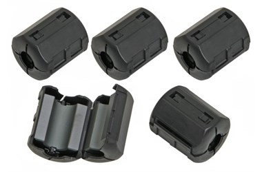
So, how to use only 3.7 meters of coax sleeve? The suggested answer is to use a clamp-on ferrite bead at that point on the coax. That is exactly what I did with the first tests.
After Joeri’s response about my previous post, and thoughts about what mattered, I responded to him that my suspicion rests with those clamp-on ferrites. Are they effective enough to do the blocking we expect?
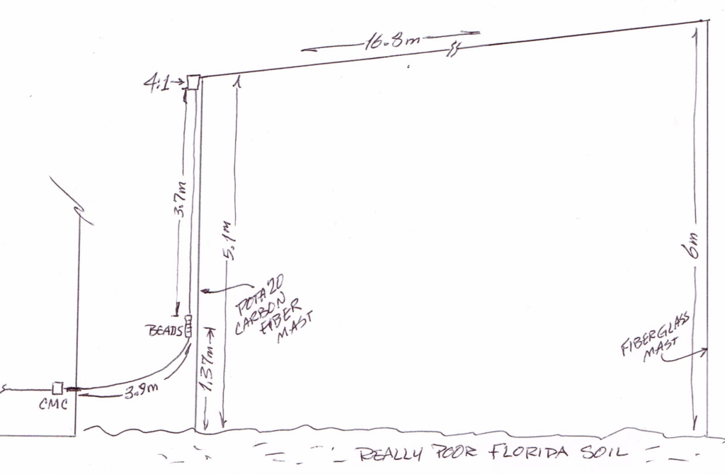
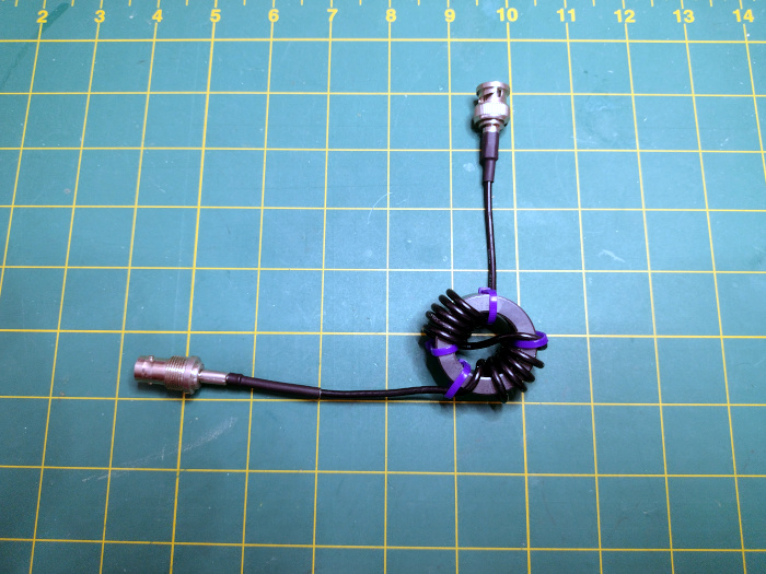
Now, let’s try again with variations. This time I’ll use two masts with the transformer and coax raised off the ground as follows. The old, broken, fiberglass mast raises the transformer and dangling feed line to 5.1 meters. A “Pota20” carbon fiber mast raises the other end of the 16.8 meter wire to 6 meters above ground. The remaining portion of the dangling coax (ABR 400) enters the shack (actually my lanai) through a bulkhead connector and is immediately met with a homebuilt* common mode choke (CMC).
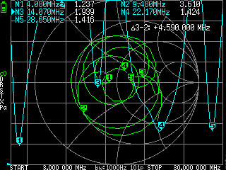
The first nanoVNA scan is with this setup and only one of the clamp-on ferrite beads. These scans are from 3.0 Mhz to 30 Mhz and show varying numbers of SWR low points. The dogleg for dip #3 ~might~ be where the coax wasn’t taped as closely to the mast as at other points.
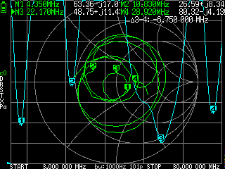
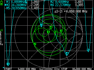
Next, add a second bead and scan again. Note point #2 is shrinking.
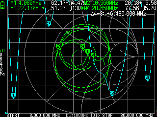
Add a third bead and scan again. Point #2 recedes further and a new #3 emerges.
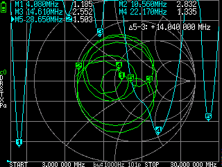
Add a fourth bead and scan again. Note that #2 is almost completely gone and #3 growing.
Add a fifth, and my last, bead. Hey, we have something almost useful for 20m.
Adding more beads might continue the changes, but I have no more. So, just “for kicks” I added yet another homebuilt CMC just outside the lanai bulkhead. Yes, that’s 2 of them back to back.

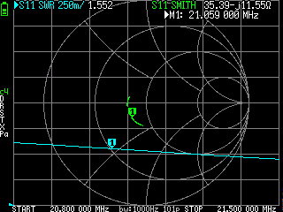
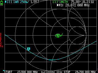
It’s very clear now that choking this part of the coax sleeve is critical, and I’m uncertain of what is “good enough.” Perhaps stopping at 5 beads is enough. OK. Let’s stop at 5 and then see what individual bands look like. Each of these shows my preferred CW part of the band near the markers. The QMX rigs will be OK with 20m, 15m, 10m.
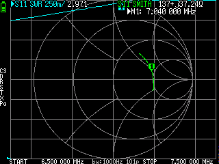
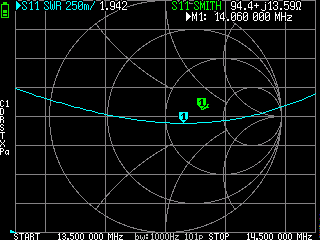
BTW… Where’s the 40m resonance point? It doesn’t show up at all on the nanoVNA. The QMX+ reports 3.6 for 40m, beyond its internal tolerance. Instead, we have a contender for 80m, a band I rarely try. At some point, I’ll try both 80m and 40m with the TR-45L’s internal tuner.
footnote: My homebuilt CMCs follow a common pattern: 10 turns of RG-174 coax through an FT-140-43 core.
UPDATE: further fiddling … further unsatisfactory results. Wasted time. I’m placing “RF Guru” Joeri in the same category as The Music Man’s Harold Hill; Charming, persuasive and a salesman. Some might buy his unproveable promises, but there’s no happy ending at the Casa Easton Antenna Test Range. i.e. My name is not Marion Paroo.
Leave a Reply