Why this idea?
Several years at this HOA QTH has found me working “backyard portable” every time I want to get on the air. That means setting up and tearing down every day. (Various night time critters are why I don’t leave antennas outside after dark.) The limitation of daytime antennas is how I became primarily a POTA Hunter (not a bad thing), but did no operating after dark. For a long time I’ve been wanting a quasi-permanent multi-band antenna that’s useful any time of day.
A few months ago I simulated a flagpole vertical (acceptable within the HOA) at several locations on the property but ended up finding the best location, appearance wise, really sucked for good performance. Hence, no flagpole; find something else.
One ham here in The Villages FL (world’s largest HOA?), now a SK, successfully used a couple of Tarheel screwdrivers for some years. So, I decided to give a screwdriver a try. At the time I started this adventure, the Yaesu ATAS-120A was an easily available choice. (NO affiliate links in any of my HAM articles)
Hey, aren’t those for vehicles?
Typically, we find the ATAS-120A antennas on RVs, trucks and other vehicles. They are successful for those uses, and my friend Nancy, KD7S, has one on her RV loves it. BTW, Nancy also likes her 650W amp. 🙂 Wander around YouTube and you can find a couple of hams who have used the ATAS-120A like a portable ground mounted vertical, on some low mount with a handful of radials.
I wondered if it would work well mounted on my home, up in the air a bit. … AND, will it work QRP?
Hey, aren’t those for Yaesu radios?
Yes, the ATAS-120A is a Yaesu product and is designed to work with Yaesu radios. Most late model Yaesus include the Up / Down control circuitry, usually with SWR sensing that makes the Up / Down movements automatic. Hit the “tune” button and watch the antenna adjust itself.
Building my own simple(?) manual controller
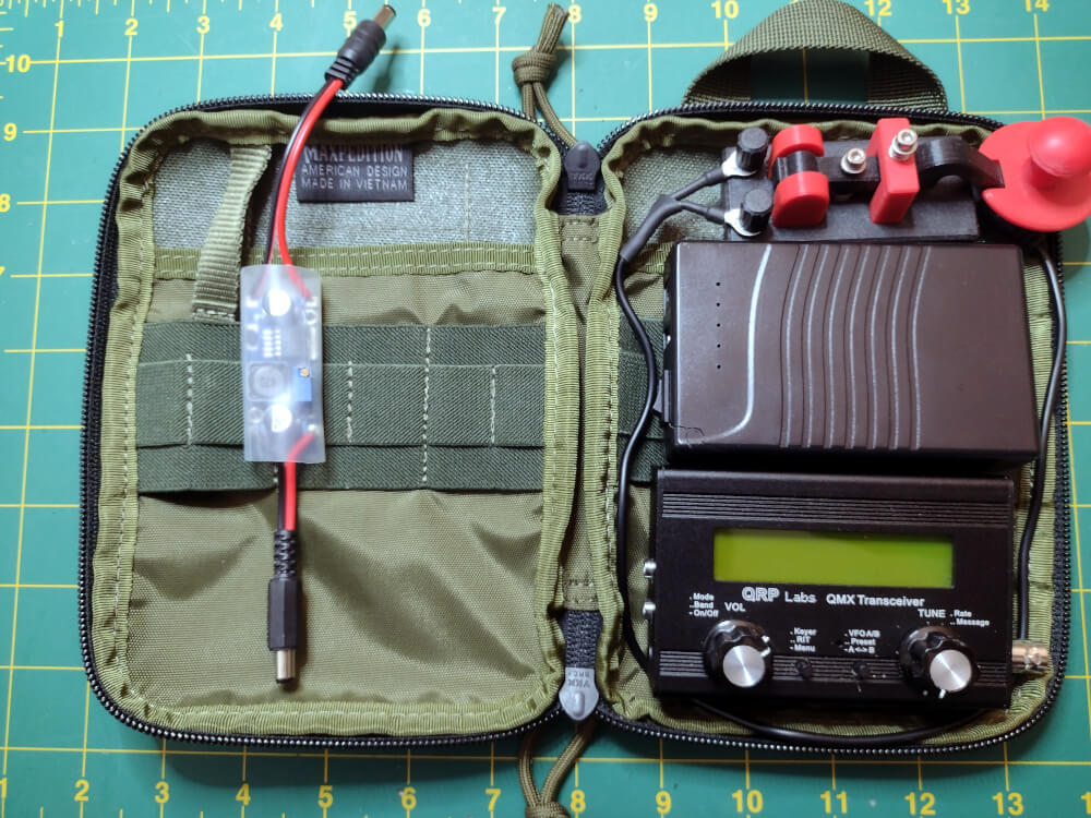
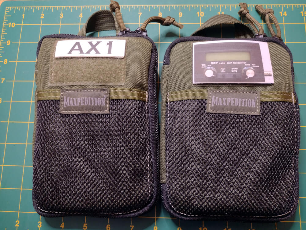
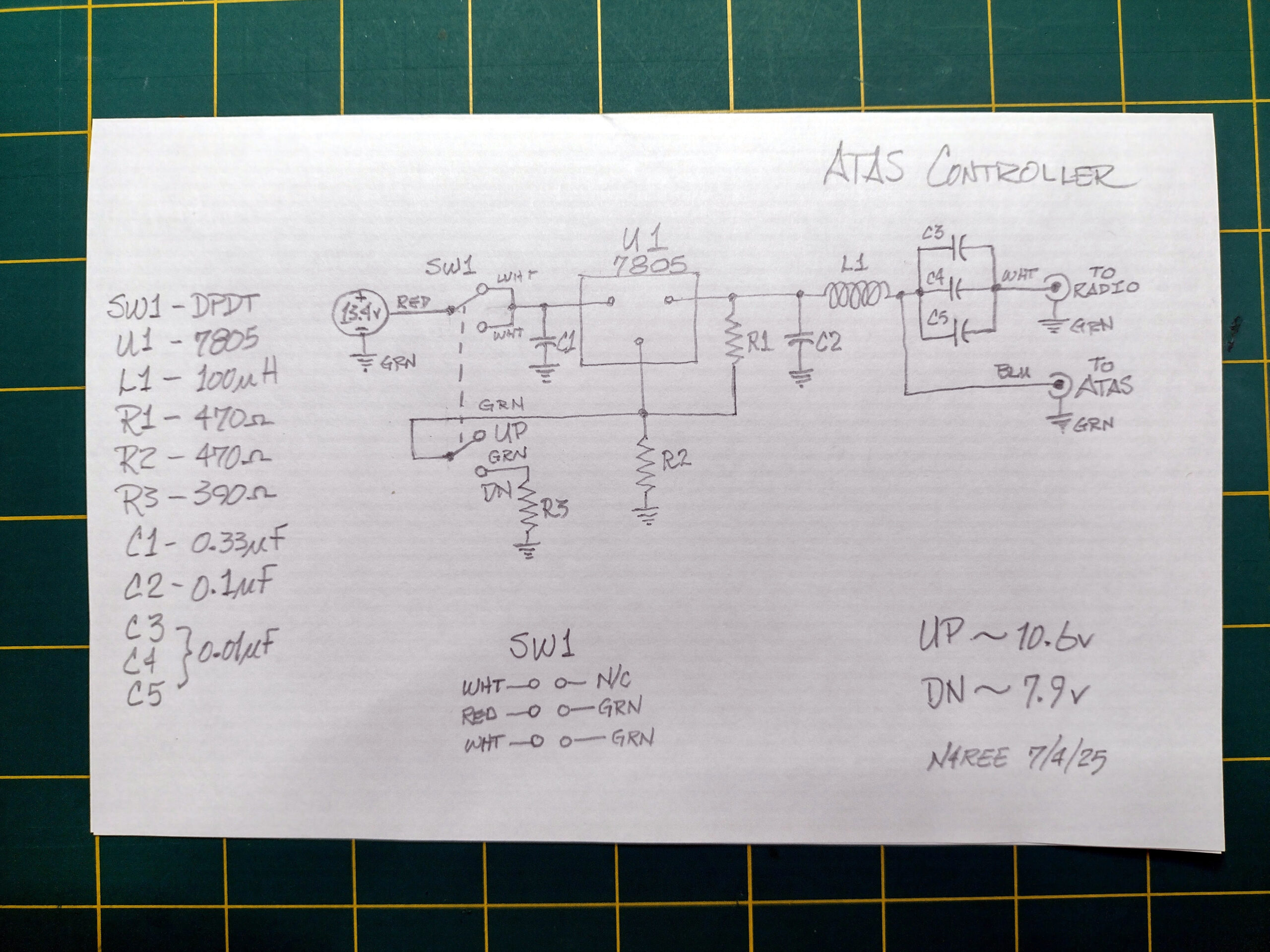
I own absolutely ZERO Yaesu radios, and my QRP Lab QMX radios certainly don’t include the Up / Down control circuitry. So, … I built my own manual controller. It derives from several articles found online and is basically a voltage divider that accepts 12v in and produces either >10v out (for Up) or <8v out for down.
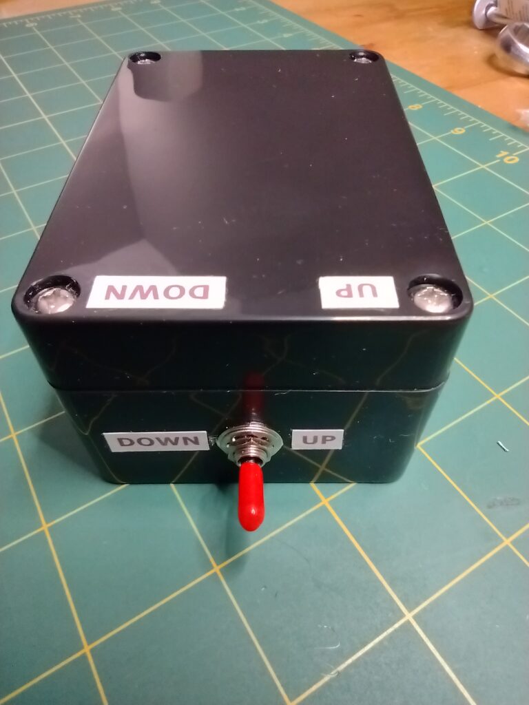
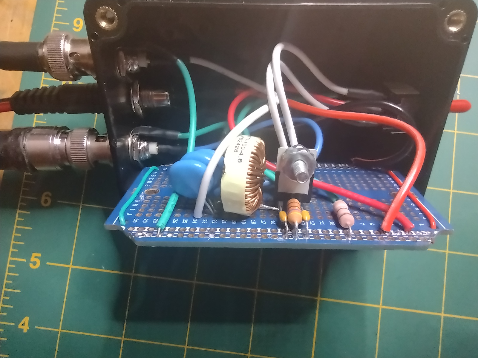
My implementation adapted a circuit I found online, and is built on a simple breadboard in a plastic project box. Use my schematic if you please, but do your own parts finding and debugging. You’ll learn from it. ;}
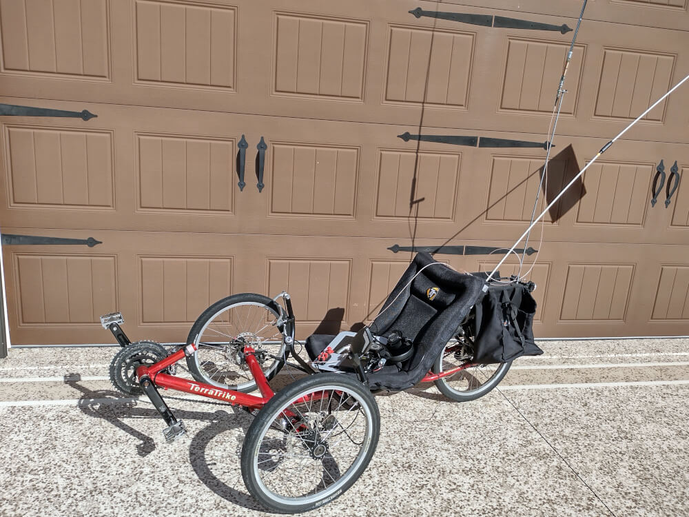
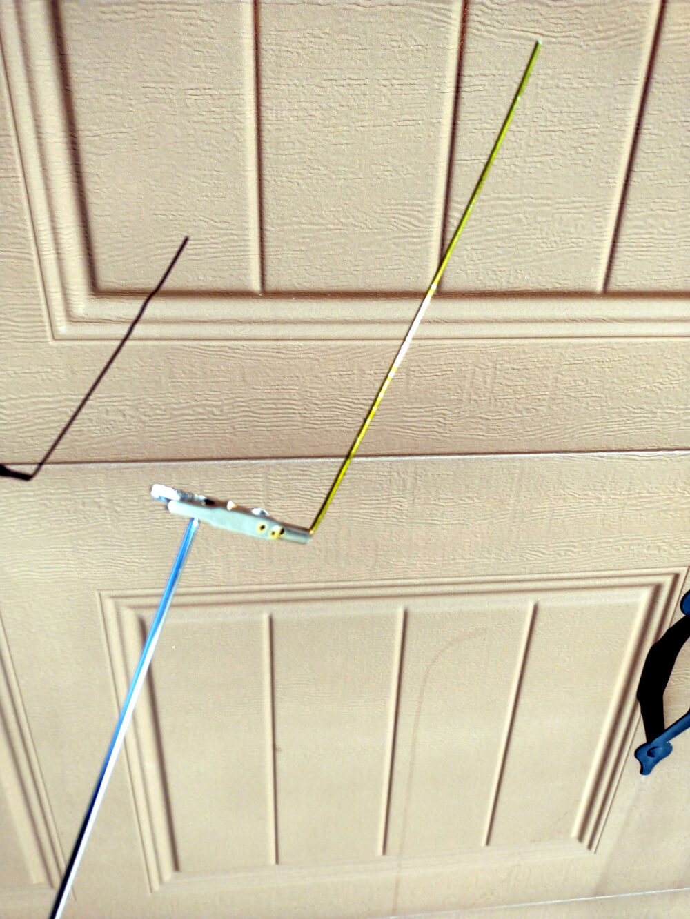
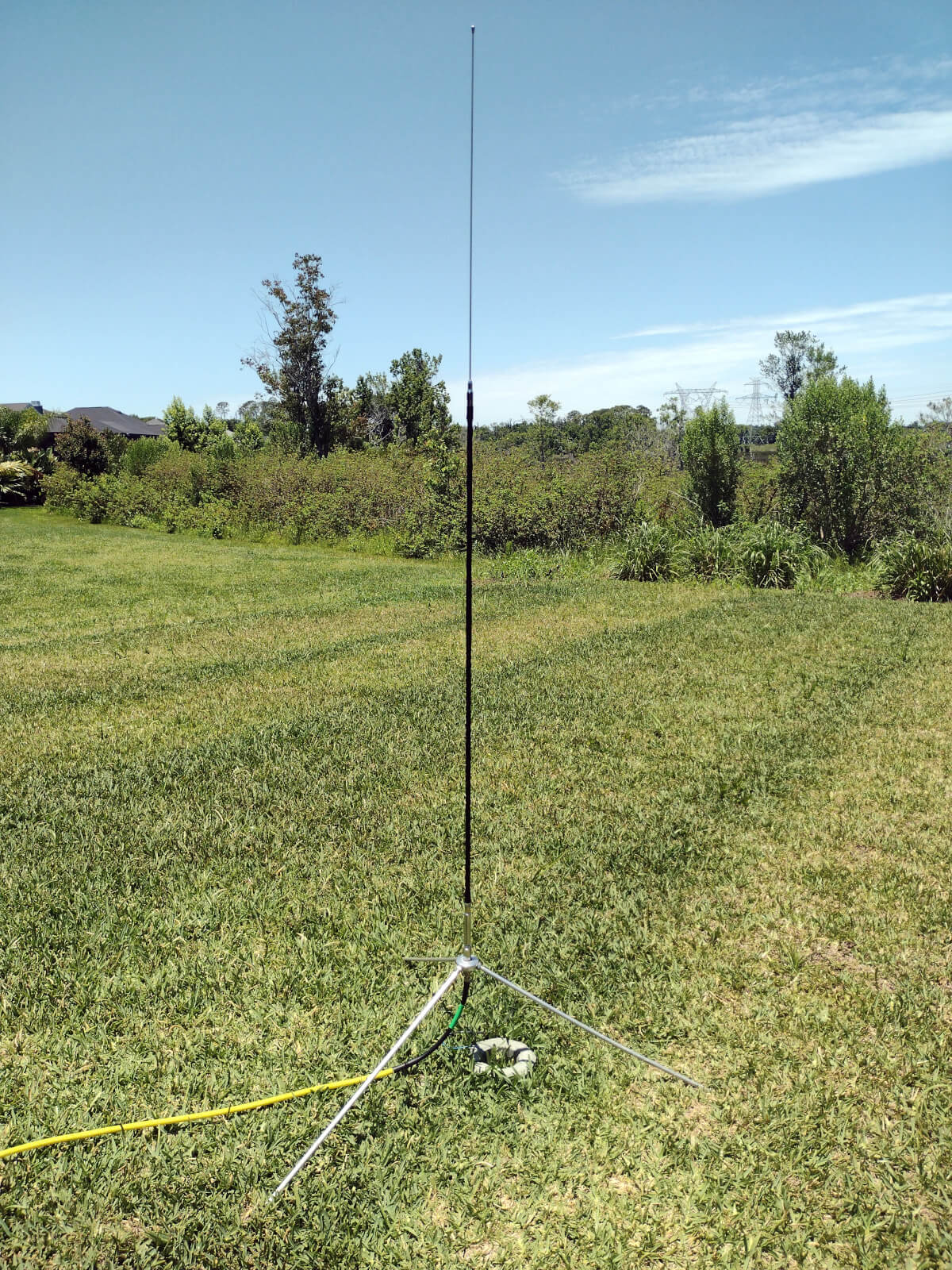
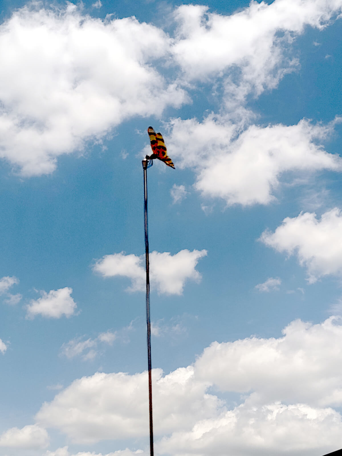
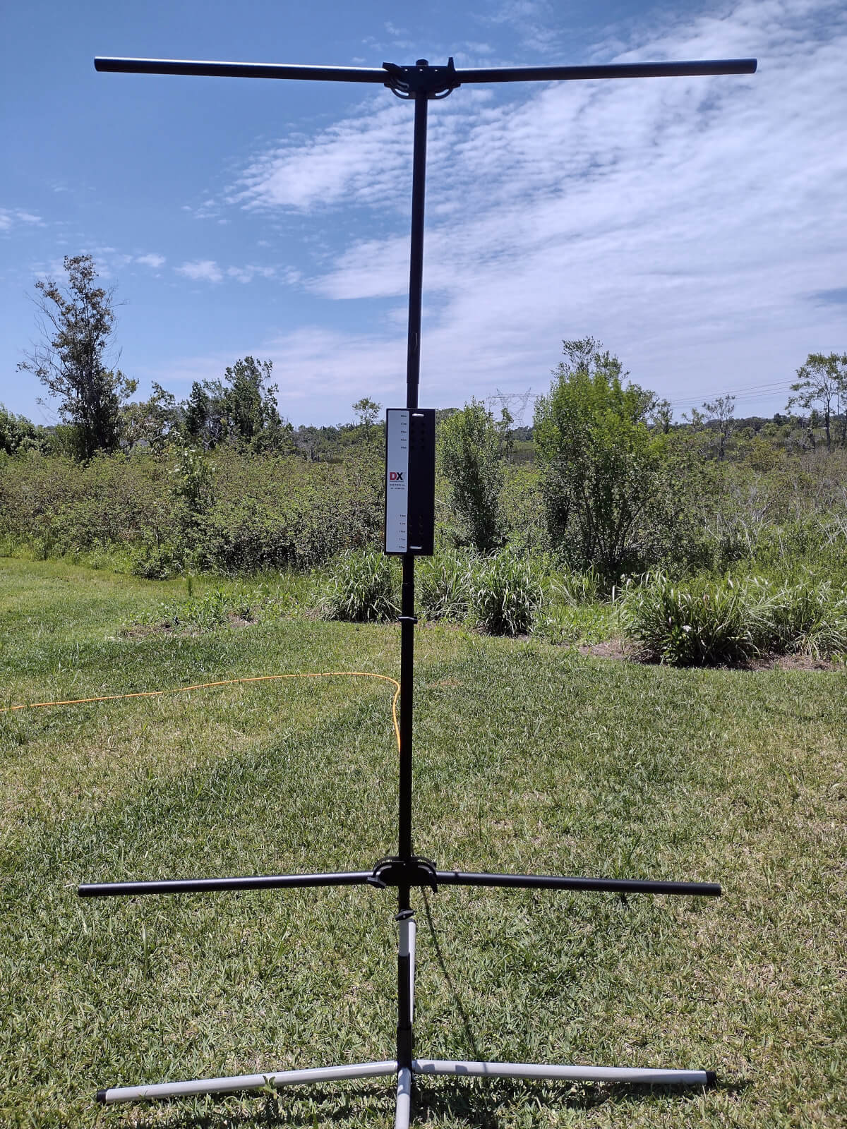
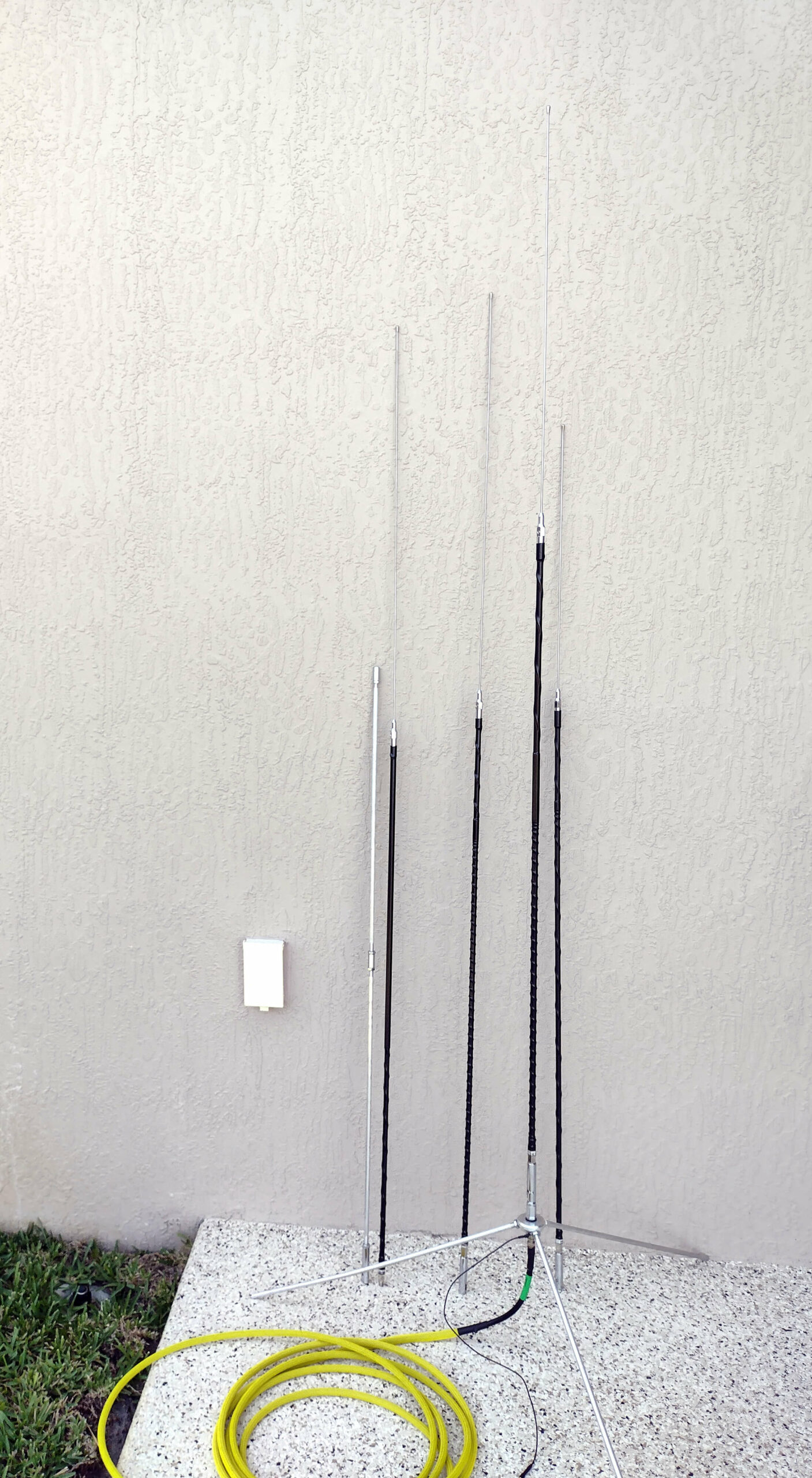
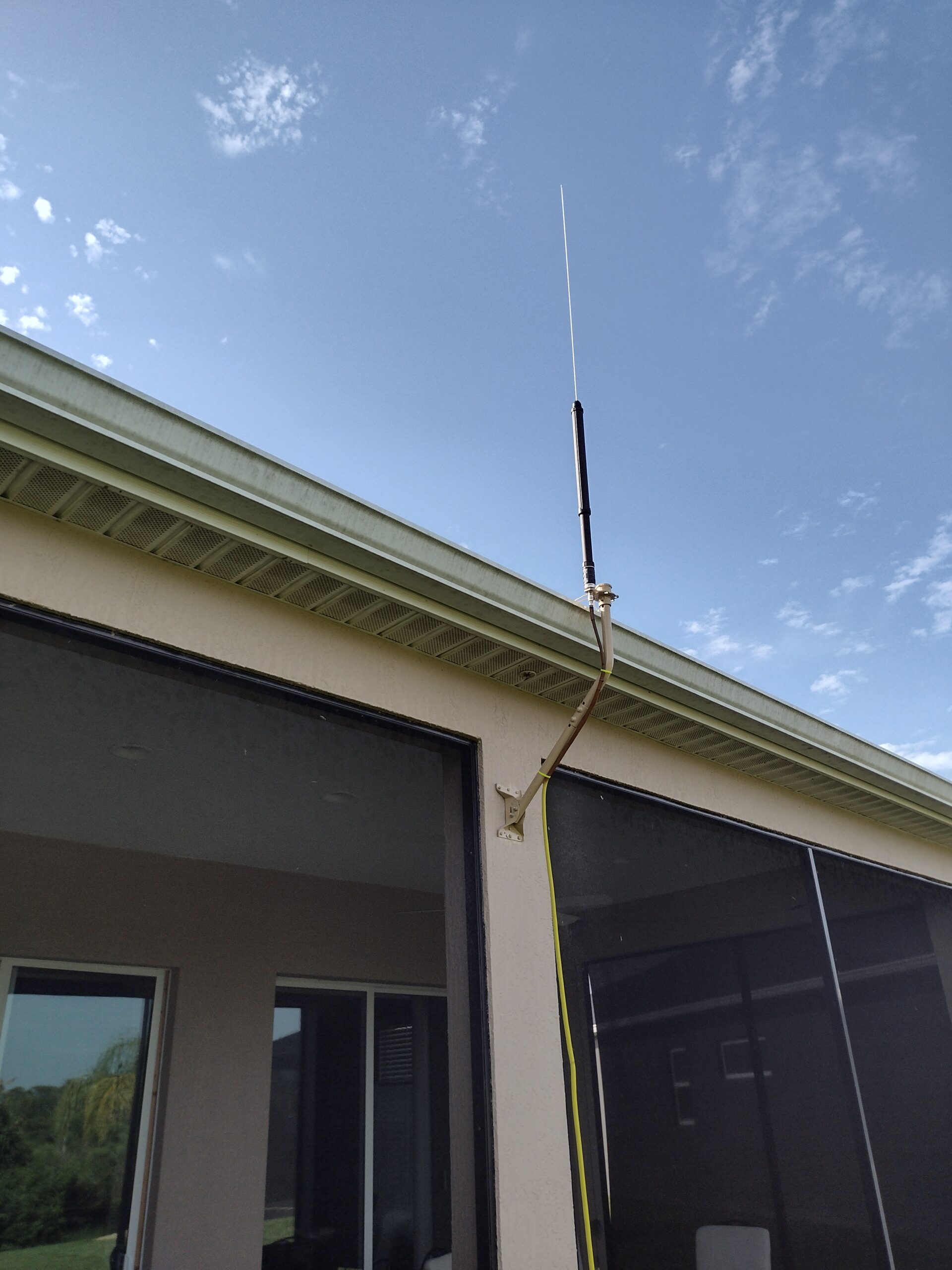
Mounting on the house
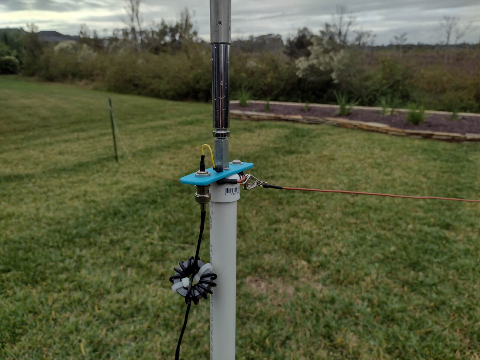
This offset antenna mast was found on Amazon when I was considering putting the lawn robot’s local antenna in an elevated position. I later ended up using a simple 6′ ground mast for that and had this mast left over for a couple of years. It is perfect for positioning the ATAS-120A at rain gutter height without being (HOA) obtrusive. A “Skyhook” mounting plate and various bits of PVC ingenuity complete the mast.

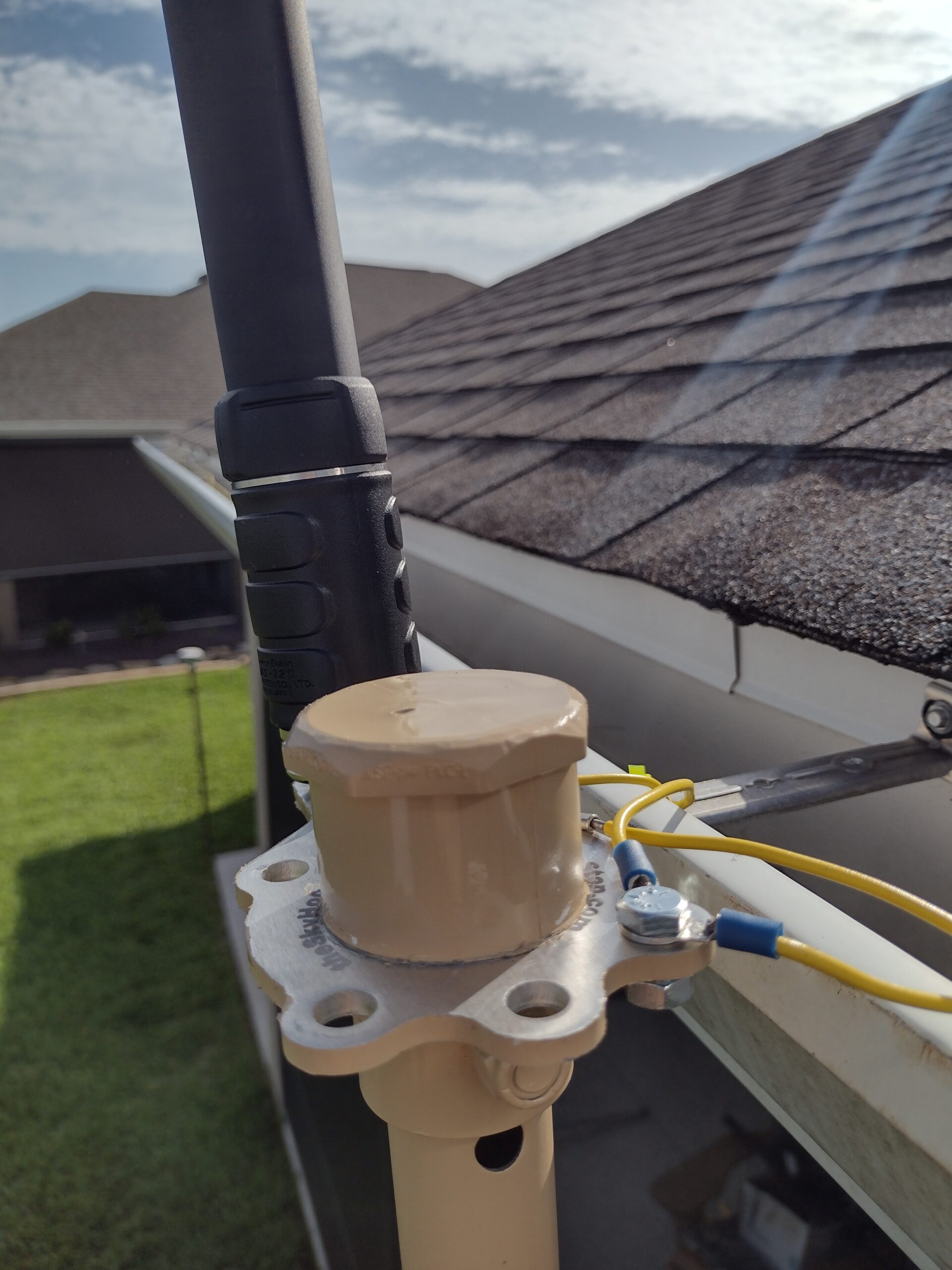
Rain gutter counterpoises
My looming uncertainty was whether elevated counterpoises could be discovered that make the ATAS-120A an actual antenna. My plan was to run counterpoises inside the rain gutters, out of sight. Yes, before you ask, I did try simply using the rain gutter system as one big counterpoise. Didn’t work; likely because of uncertain continuity between different sections.
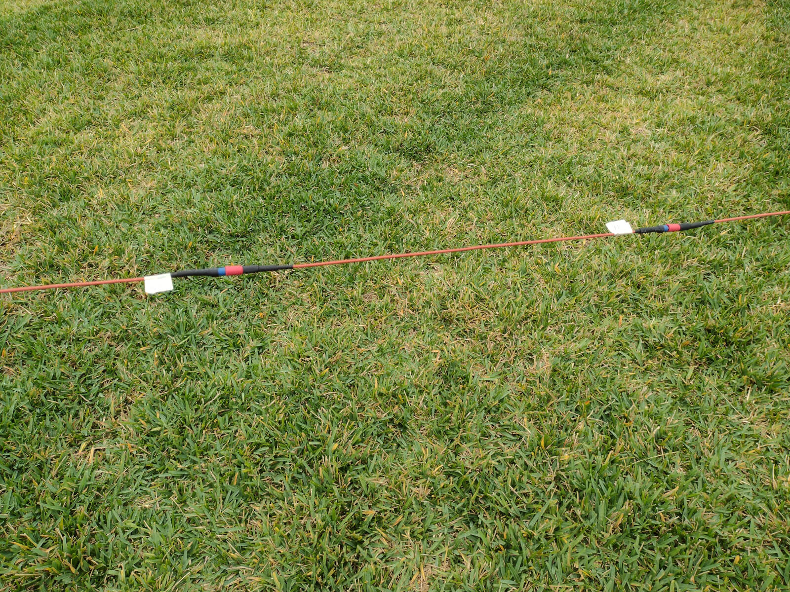
My experience with raised counterpoises for the KJ6ER PERformer Vertical Antenna paid off in guessing at good lengths. There’s still part of a spool of insulated stranded copper 14 AWG left from previous experiments at the Casa Easton Antenna Test Range. I started with two 16’9″ counterpoises for 20M and found SWR on 20M was WAY out of bounds. Adding two 33’5″ counterpoises, typically for 40M, brought a lot of SWR harmony. Each of the wires is strung through the gutters, sometimes around corners, and zip-tied semi-taut to the gutter cross braces.
SWR readings near or below 2:1 magically appeared for every band I care about. Maybe this thing will work after all? Maybe it still wants more counterpoises?
First measurements
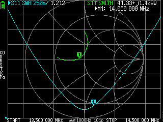
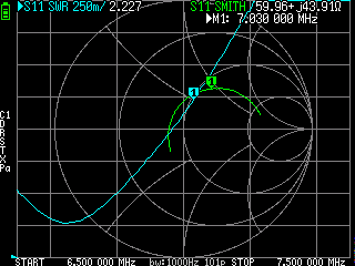
I make SWR measurements 3 ways:
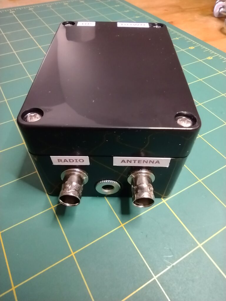
- Through the controller. With the antenna connected to the controller, and a NanoVNA connected to the “Radio” port, I maneuver the antenna up or down for the best reading at my desired frequency, usually the QRP CW watering holes for each band.
- Once a sweet spot is found, I disconnect the antenna from the controller and measure directly with the NanoVNA. There is a DC blocking network in the controller, L1 and C3, C4, C5, that isn’t completely linear and affects readings.
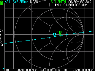
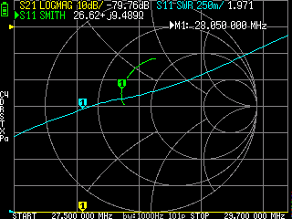
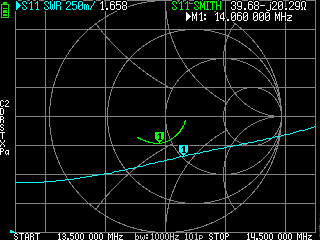
- Leaving the controller out of the circuit, and the antenna connected directly to a QMX, the Hardware > Tune function provides yet another SWR reading. This one is often very close to that of the NanoVNA. These are the SWR readings that suggested this antenna might act as an antenna. The first SWR reading is with the controller inline, the second without. I didn’t include the 3rd way of measuring in this chart, but use it when on the air later.
- 7.040 – 2.062 / 1.784 – 31 Ω
- 10.110 – 1.765 / 2.060 – 78Ω
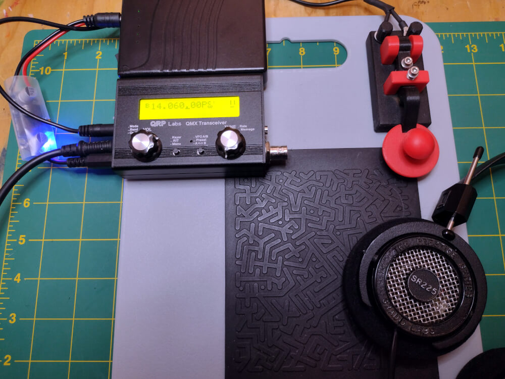
- 14.060 – 1.760 / 1.295 – 39 Ω
- 18.060 – 1.153 / 1.840 – 57 Ω
- 21.060 – 1.649 / 1.214 – 43 Ω
- 28.070 – 1.675 / 1.149 – 43 Ω
Does it “antenna?”
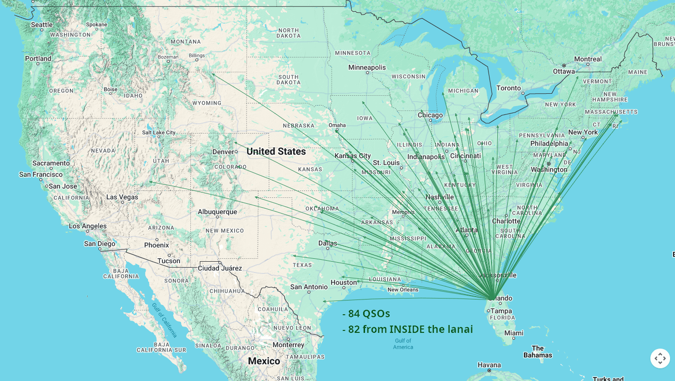
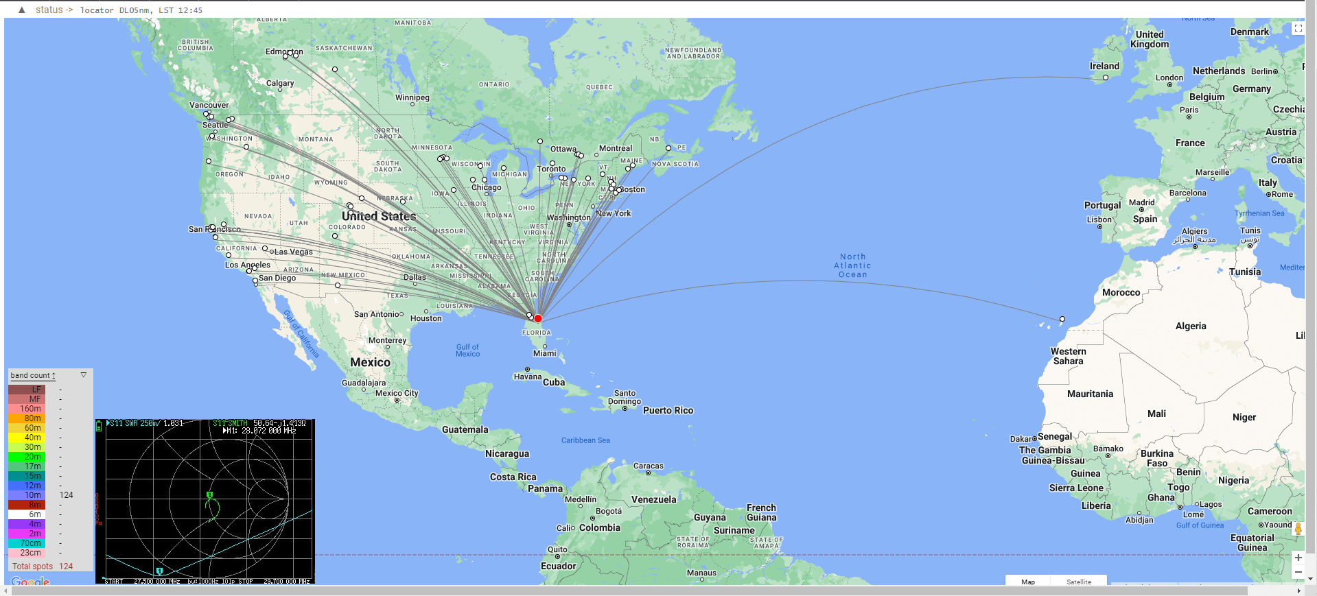
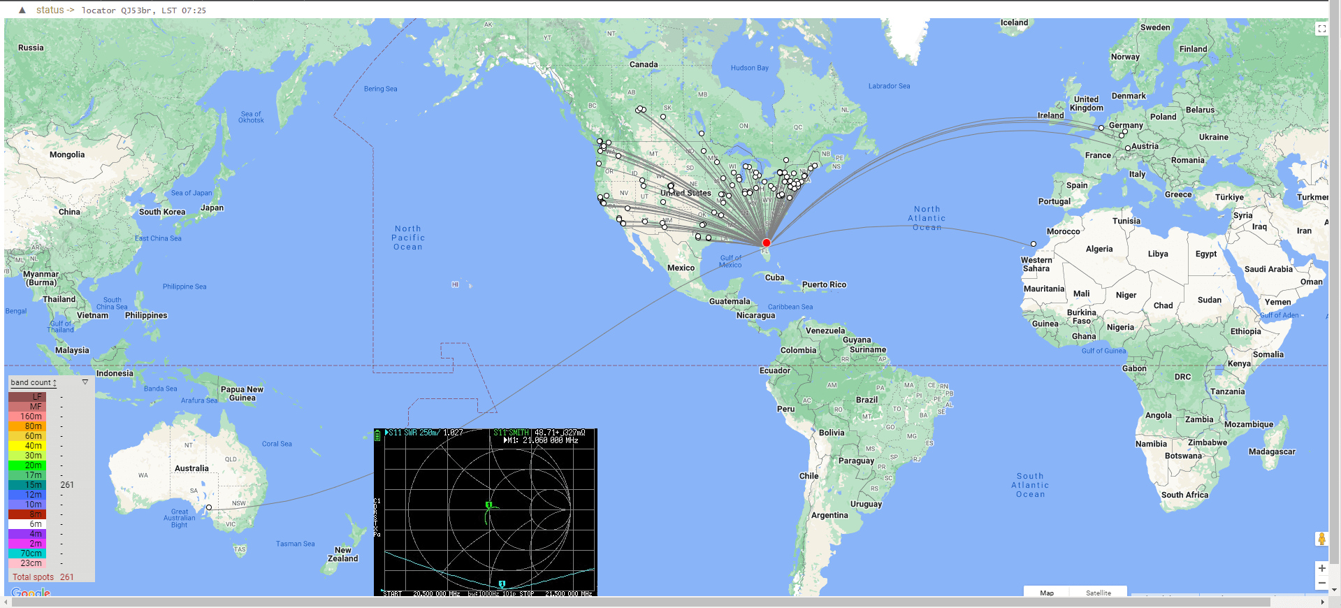
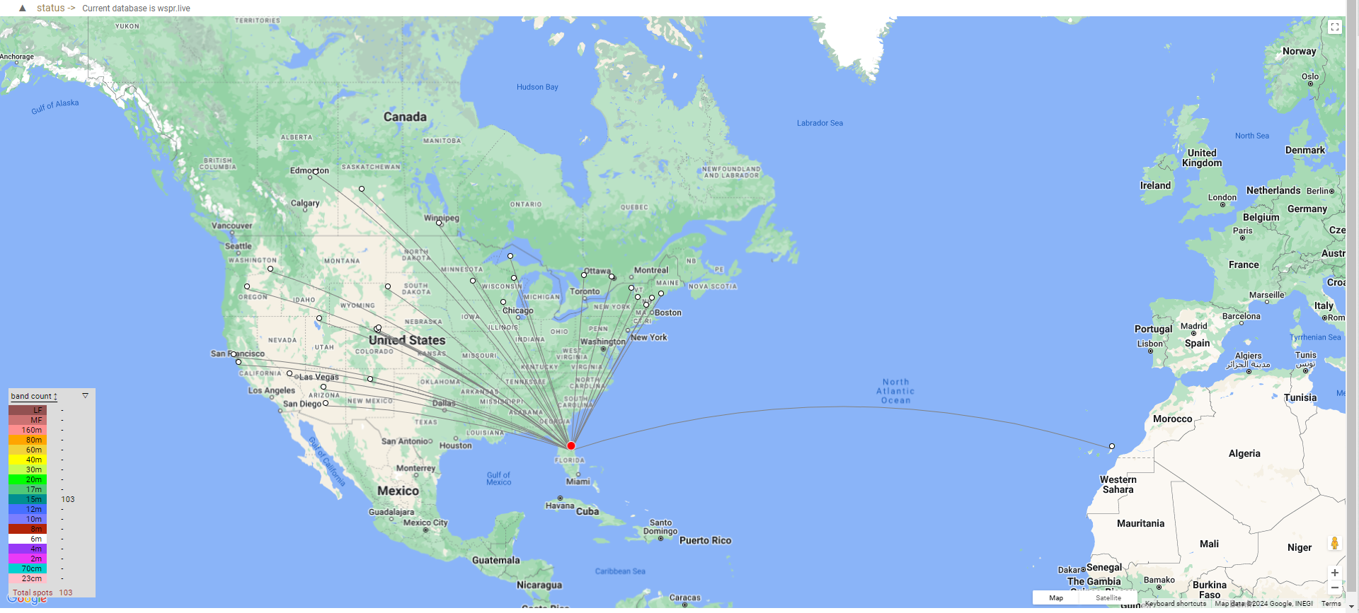
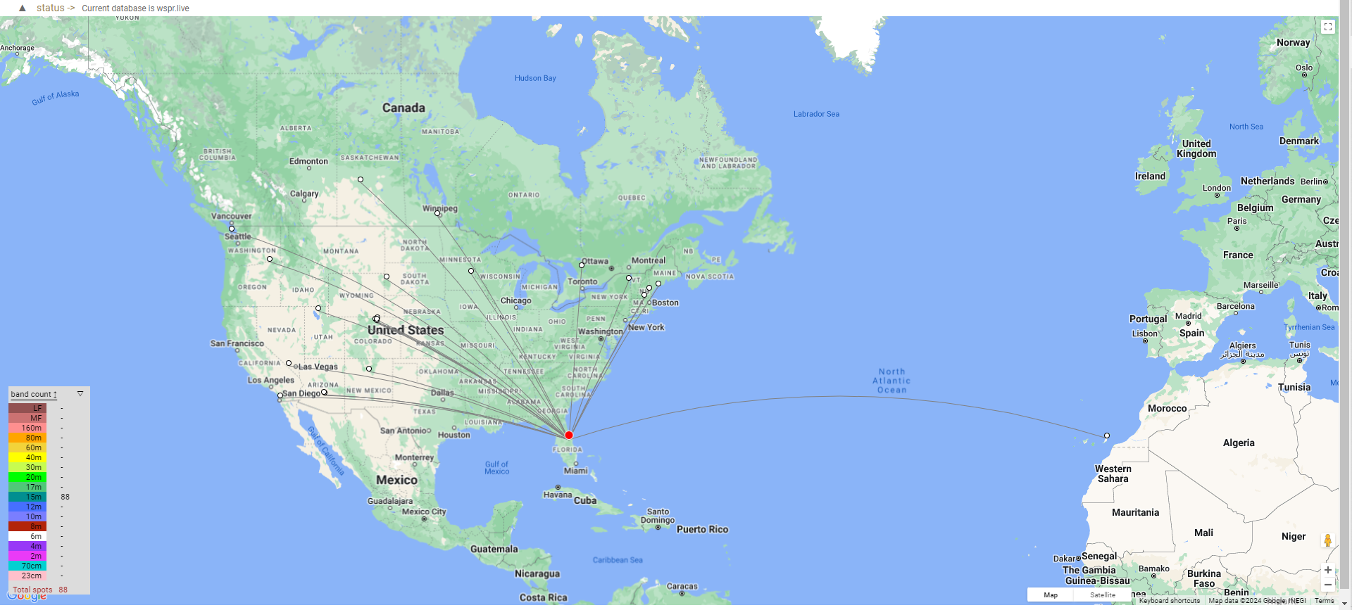
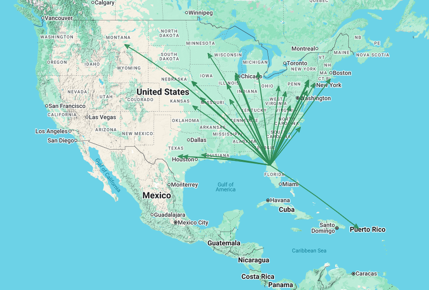
When I’m completely rigorous, I do a big pile of WSPR runs. So far, only a couple of runs on this antenna, I ran the first with my ZachTek WSPR transmitter, 0.2 w, for 10 minutes at 16:00z on 7/17/25, while we were in a G1 geomagnetic storm with a K-index of 5. The results were 45 spots scattered through mid-USA with the western-most in LA California and the north-eastern-most near NY City. Not the best I’ve seen, but a good start for a very poor propagation day.
How bad was the propagation? So bad that I gave up trying to reach Oregon and mopped the floors in the house. 🙂
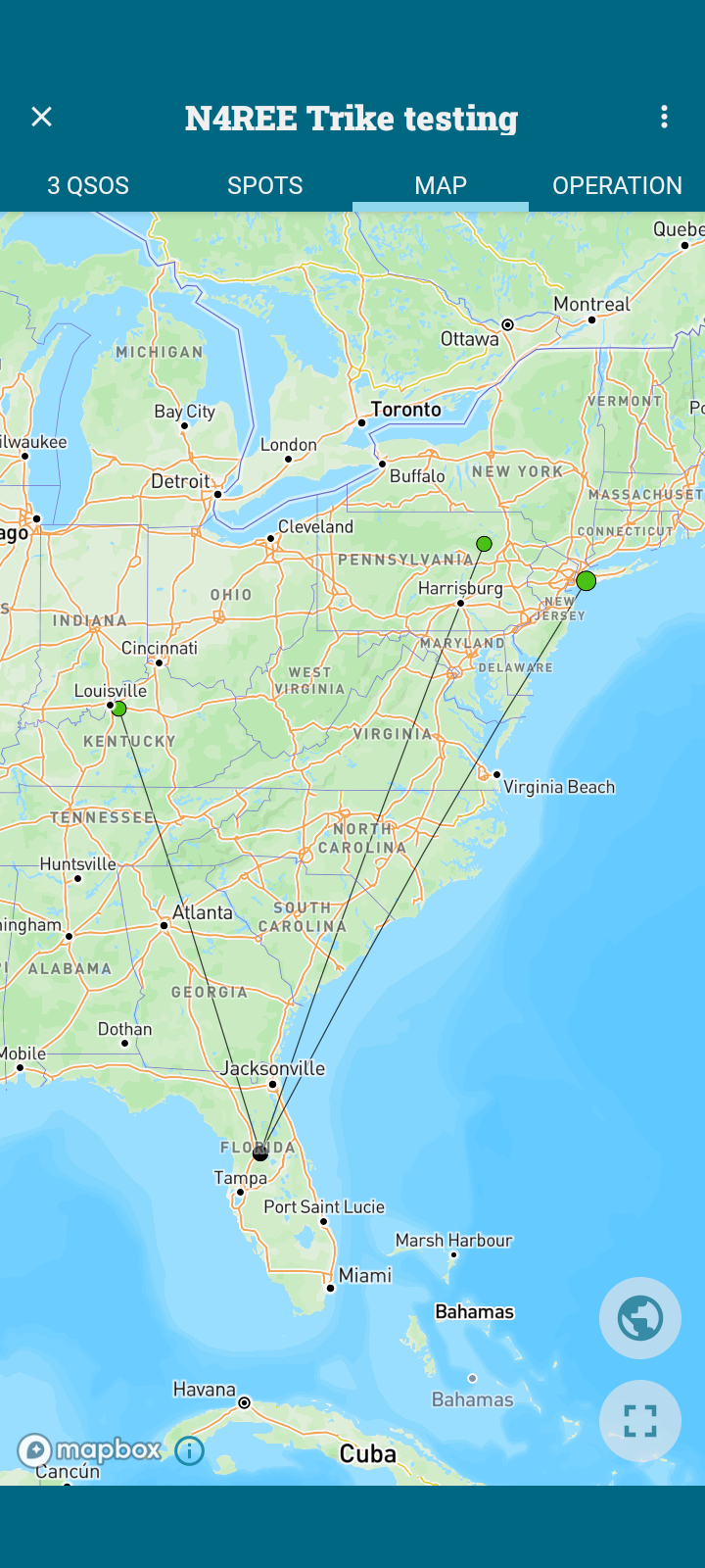
Two casual POTA QSOs today proved it does indeed antenna. POTA got me a 539 response from WQ0A Brian Foltz in Kansas City KS. Later in the afternoon, I made one of my very frequent QSOs with WB0RLJ Jim Vaughn in his favorite Chalco Hills Nebraska park. He’s one who gives accurate RST reports and I was surprised with a 559. Both my sidewinder key and my new antenna were working well.
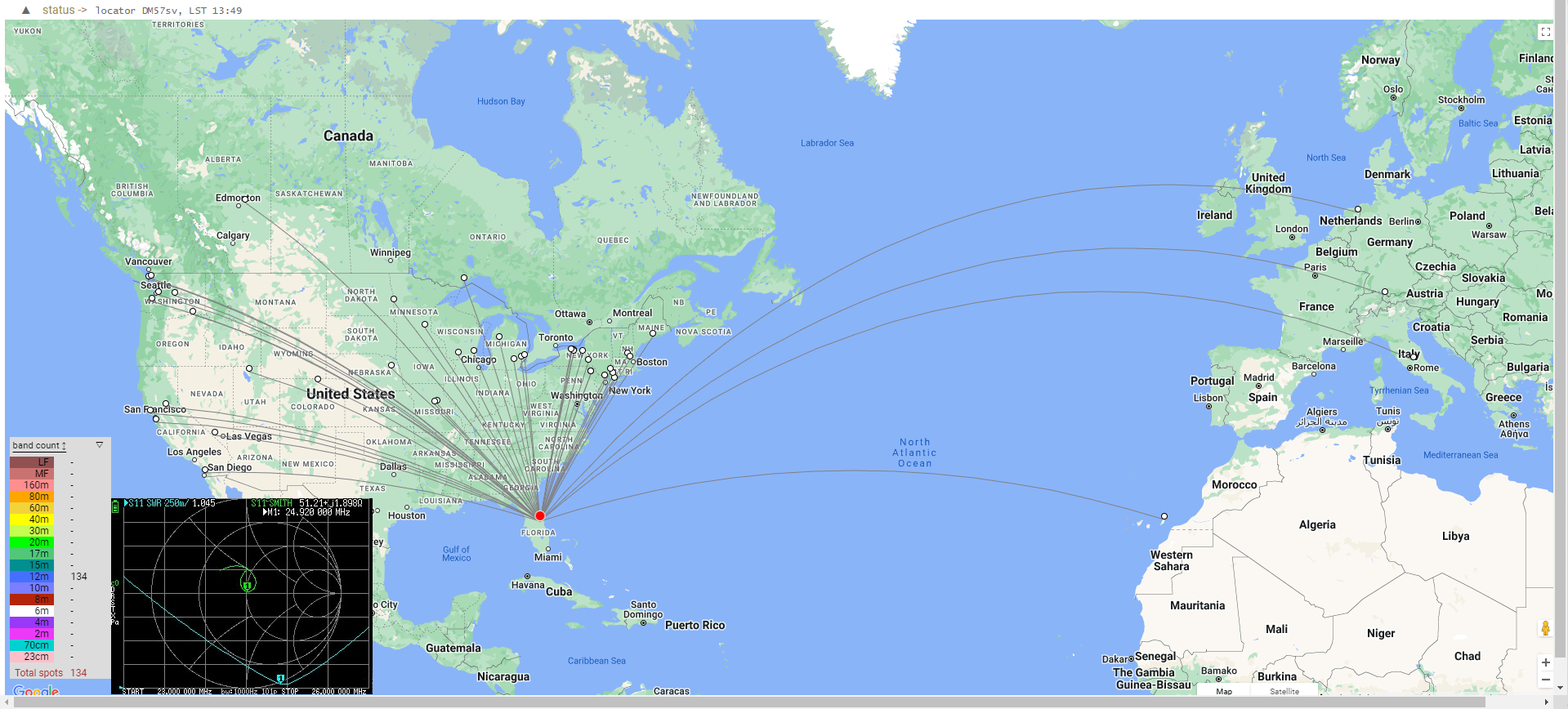
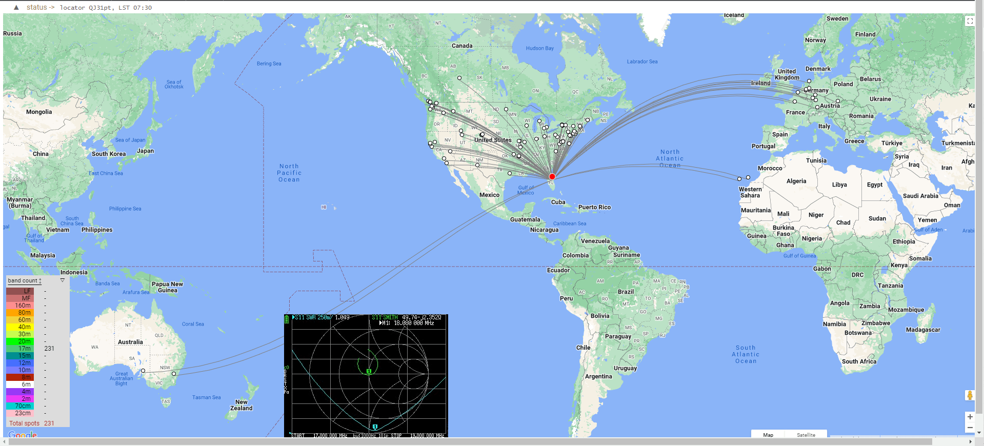
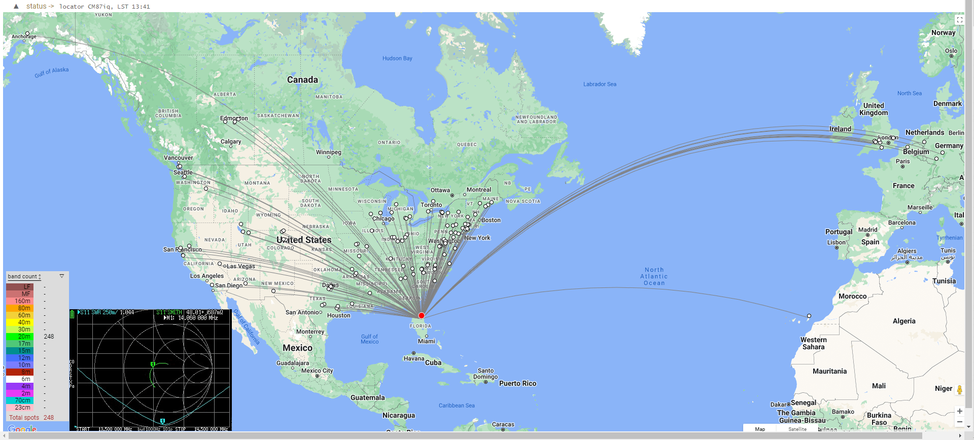
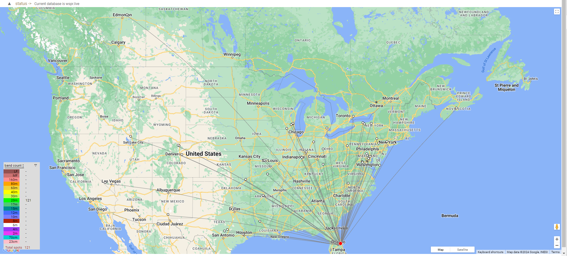
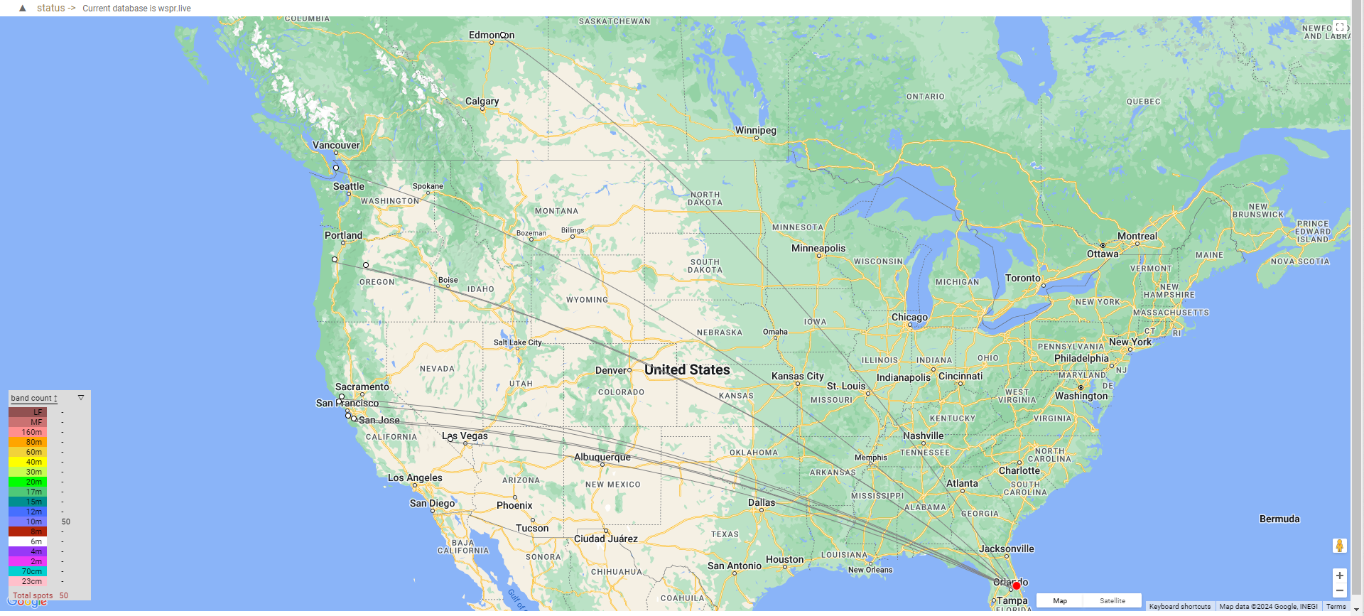
Early AM 40M – still dark. Tuned for 40M, found the band quiet, so sent some CQs into the wild and watched the RBN to see where they landed. Better reach than I expected. Pre-dawn 40M WSPR shows hits all over the USA and on up to Edmonton. Significantly fewer after dawn, as expected.
Too early to tell summary.
A few WSPR runs, 2 QSOs, and some RBN hits aren’t a lot to go on. I’ve watched the YouTube “influencers” gush over new gear with less on the air experience. Yet, so far this performance is very promising for a casual, admittedly compromised, antenna. Will it fetch DX? Nope, but it will be far more available than those that need daily setup and tear down.
Epilog
It’s been up and on the air for a few weeks. I’ve tweaked the counterpoise a few times resulting in only minor SWR improvements. It has given me 2 QSOs on 40m 22 on 20m and 1 on 15m. Overall, it hears well but is soft spoken. Yes, much of that is do to my QRP practices. Most of the ATAS fan boys run much higher power with this antenna. One influencer who really likes it demos it with a 100w transceiver, and of course makes lots of contacts.
It hasn’t met my permanent install, base antenna, expectations, so I took it down. Maybe someone else can make something of it, using it on a vehicle as it was designed, or with higher power? Besides, the XYL thinks it’s time for this 80 year old OM to stop climbing ladders.
Update – Oct 30, 2025
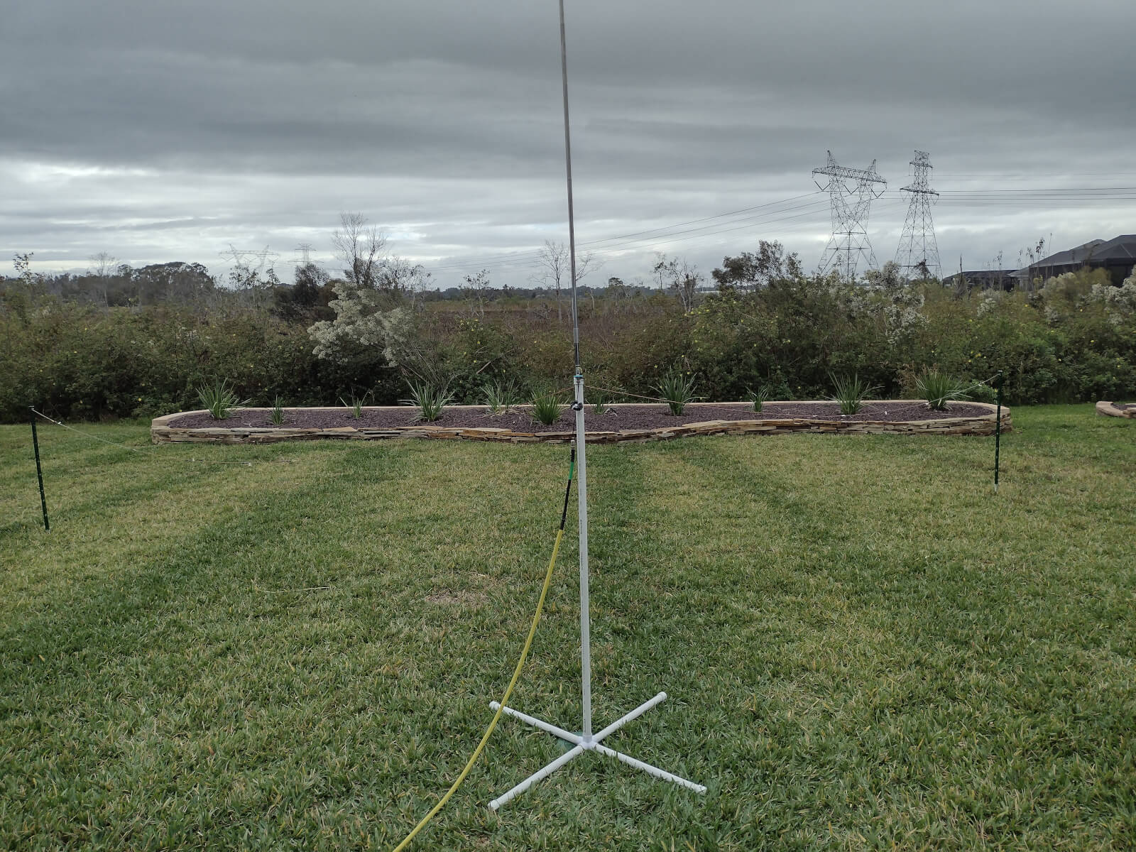
The ATAS has been in semi-retirement for a few months, and the holes in the house have been patched. Today, I tried it in a different configuration, on a ground stake in the middle of the Casa Easton antenna test range. I used 4 16.5′ radials and 4 33′ radials, making the radio very happy with SWR.
As before, the antenna hears well but still speaks softly, reaching OK and TX on 20M CW today. It really needs more than my 5 watts, and I expect it will do very well with the typical 100w rigs. Perhaps someone in the local club K4VRC will put it to better use.
Nov 14, 2025 – Indeed, a fellow club member, who already has one ATAS-120 on a vehicle wants another for a second vehicle. The antenna found a good home.