Nuff said. Because you can’t really say anything on FT8.
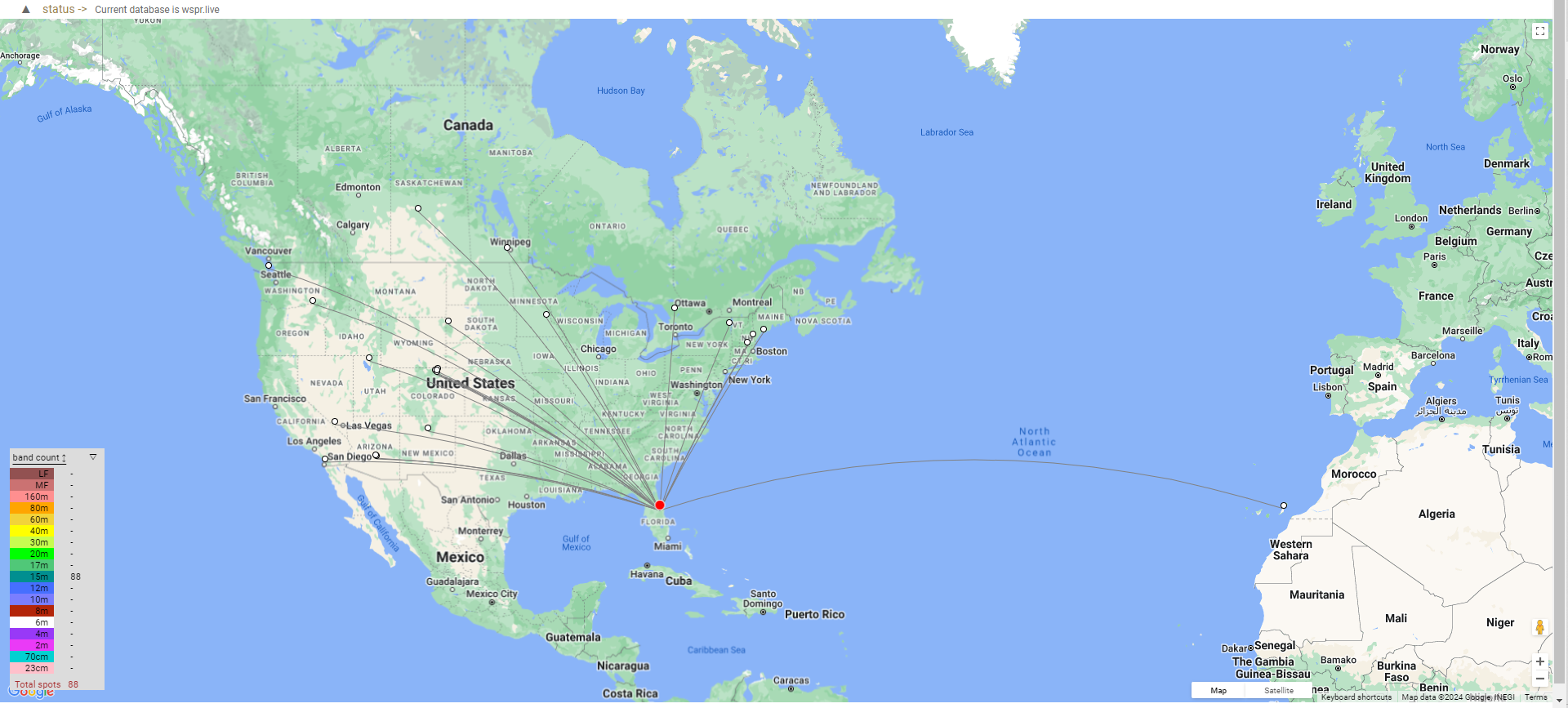
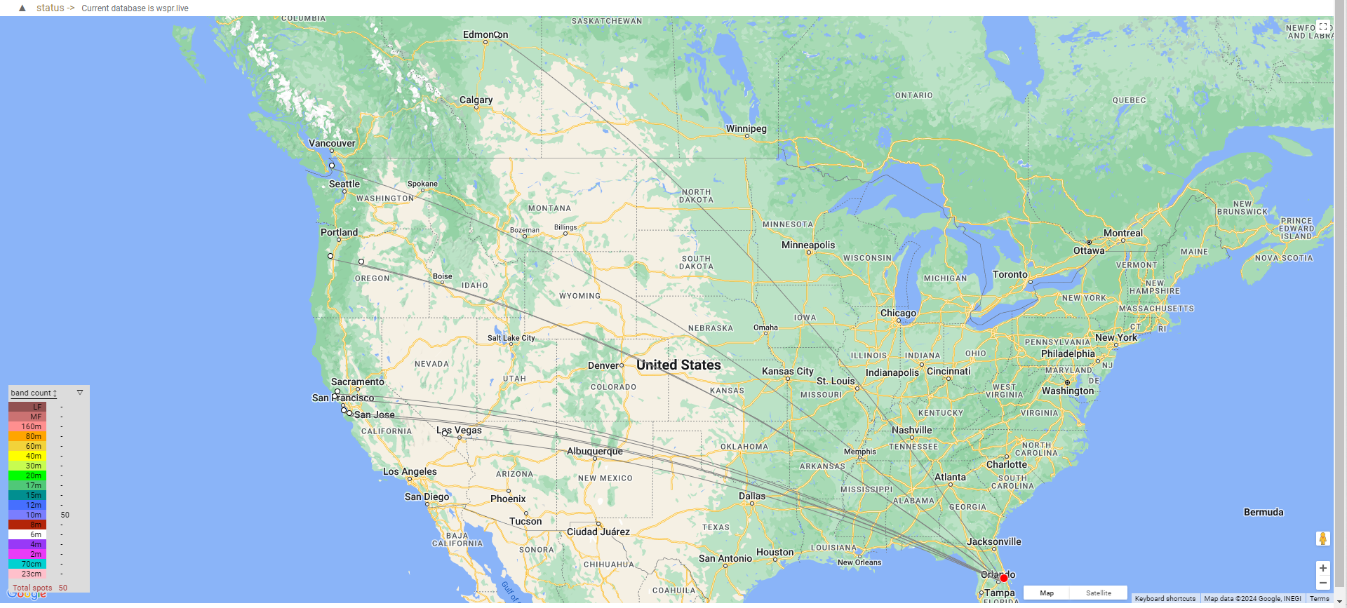
jason VE5REV responds: Like callsigns & signal reports? Can we exchange that information with FT8? Can we see propagation patterns with minimal power?? Can we use it when other modes won’t work due to bad band conditions???