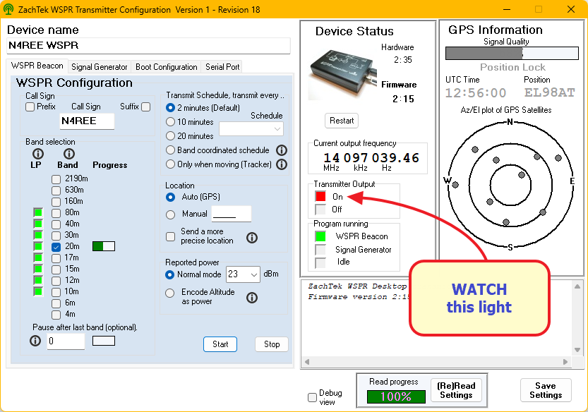
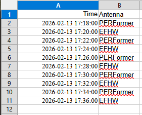
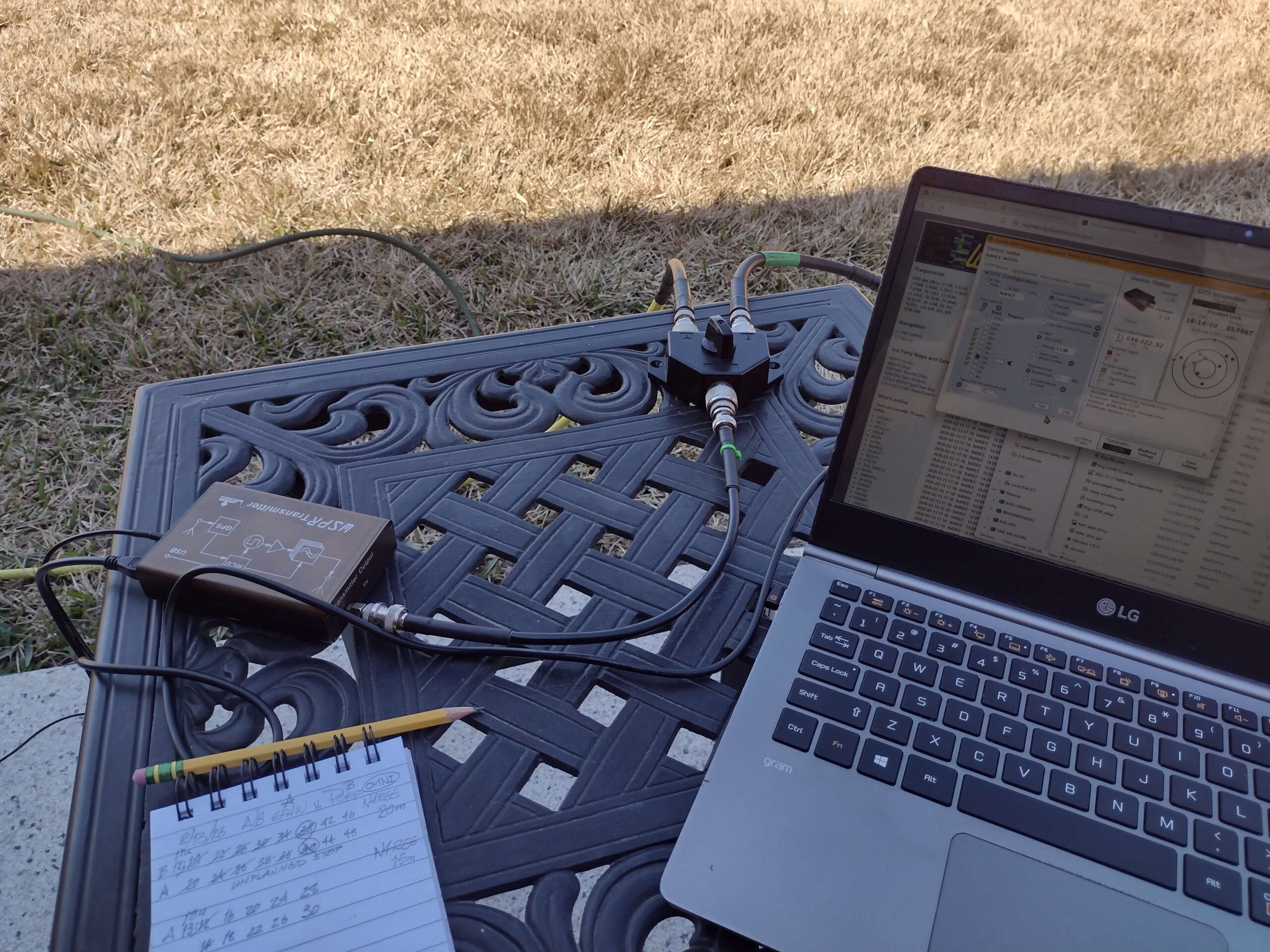
A/B antenna testing is always plagued with the “propagation constantly changes” remark that suggests the tests at different times are never equivalent. The technique I use here compares 2 antennas over the SAME timeframe, not two separate timeframes. I do this by switching the antennas back and forth for multiple 2 minute WSPR cycles as shown in part 1. That closes the gap on the changing propagation argument. THANKS to Lord Callum McCormick, M0MCX, for showing this technique.
Then, I Take the results from those runs and use AI (Grok is my AI choice) to do the grunt work of separating the 2 minute runs and analyzing the results. See part 2 for how that is done.
This post describes how the antennas are setup and points to complete results for tests run on 3 bands: 20M, 15M, and 10M.
EFHW
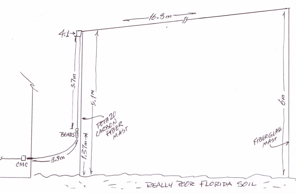
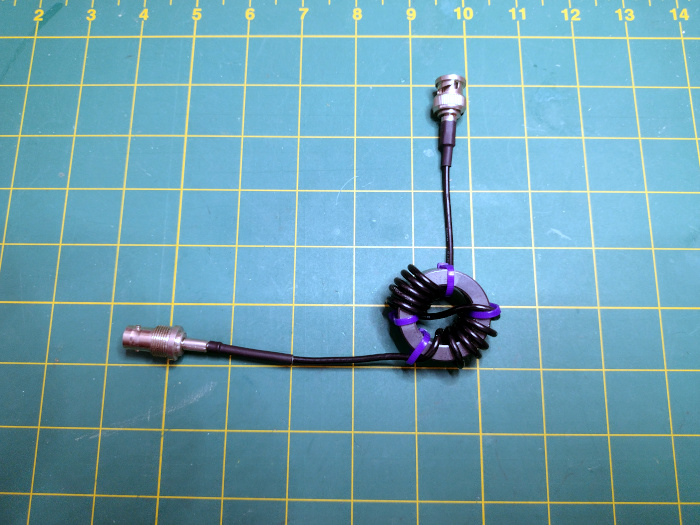
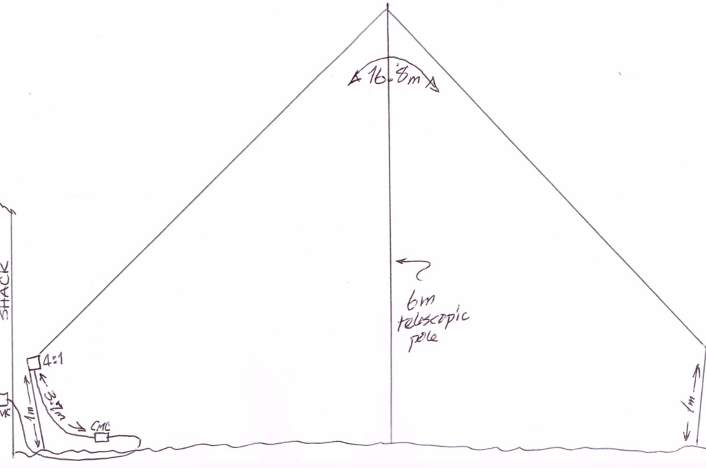
This EFHW is my everyday multi-band choice here at the Casa Easton Antenna Test Range. It consists of a wire approximately 62 feet long poised in an inverted vee form with the apex at about 20 feet, supported by a carbon fiber mast. There is a small coil (about 1uH) 7 feet from the feed end to balance the resonant nulls to where I expect them, the CW portions of the bands. It is fed by a home-built 49:1 autotransformer and that is preceded by a home-built Common Mode Choke.
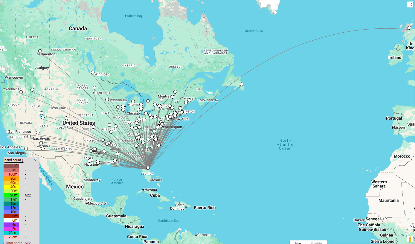
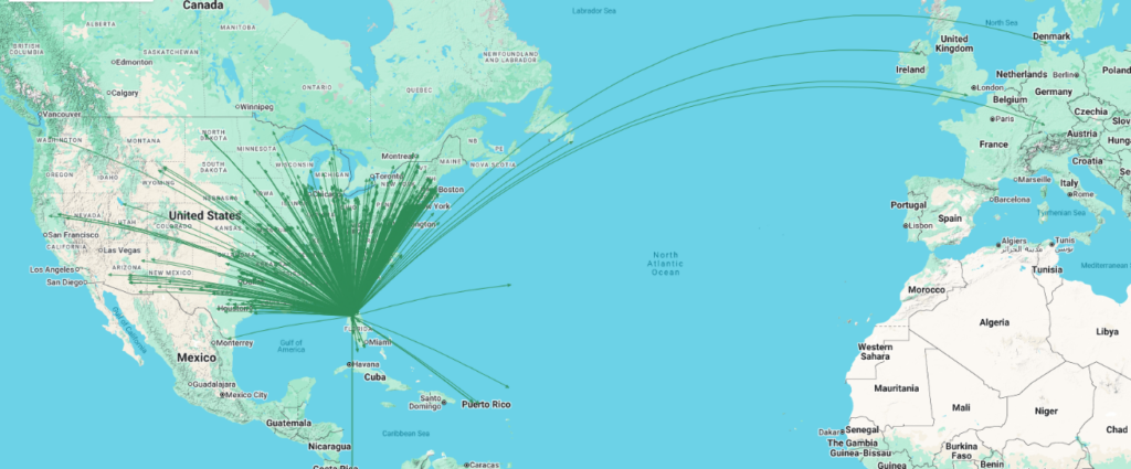
I use it nearly everyday because it is easy to deploy (my antennas are all daytime-only) and band switching is done from my rig without any physical antenna manipulation. Simple, it works acceptably well for my favorite activity, POTA chasing. It can’t always reach the West Coast from central Florida, but covers a good part of the USA.
POTA PERFormer
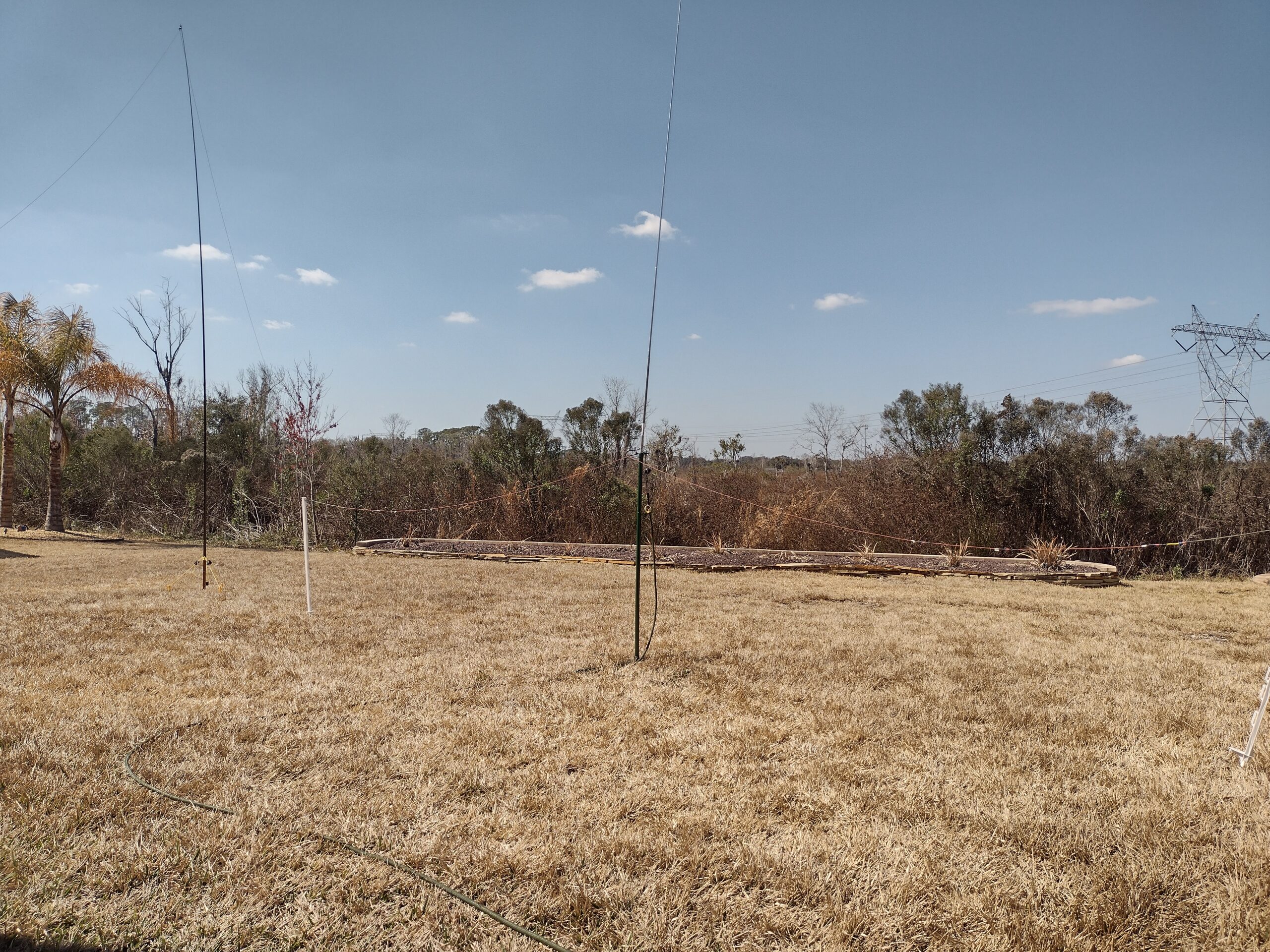
Greg Mihran, KJ6ER designed the PERFormer antenna. It is basically a quarter wavelength raised vertical antenna with two tuned, and linked, raised radials. Find Greg’s very complete description here. I built my PERFormer as close to his specs as I could. The vertical element is a 17 foot Chameleon whip. For these tests, I used the linked radials as appropriate for each band. The photo shows it and the EFHW. Radials were in a straight line running North-South.
Before anyone asks about the power lines in the distance, about 100 yards away, they are operated by Duke Energy and are completely free of any HF RF interference. Now, those plants in the raised bed are a different story. They are victims of an unusual hard frost here in central Florida.
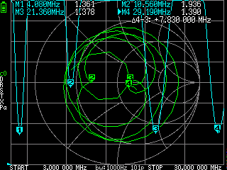
Results: Each of the links below includes the prompt I used for Grok and Grok’s full response to those prompts. Quick bottom line: the PERFormer outperforms the EFHW on 20m and 15m, while the EFHW performs better on 10m. Caveat: 10m is always a crap shoot from here.
- Complete A/B results for EFHW vs POTA PERFormer 20 meters
- Complete A/B results for EFHW vs POTA PERFormer 15 meters
- Complete A/B results for EFHW vs POTA PERFormer 10 meters
There are other A/B comparisons I might run. The physical constraint is both antennas should be different shapes. Running 2 verticals against each other in the confined space of the Casa Easton Antenna Test Range will interfere with each other. Yet, the EFHW vs a Marauder or a Marauder vs a TW2010 might work. Perhaps…