• Skip to primary navigation
  • Skip to main content
  • Skip to primary sidebar

N4REE - Minimalist Ham

Code rehab forever - Make CW a 2nd language

  • Home
  • About
  • Contact

radio

QMX+ First run

April 11, 2025 by Bob Easton 2 Comments

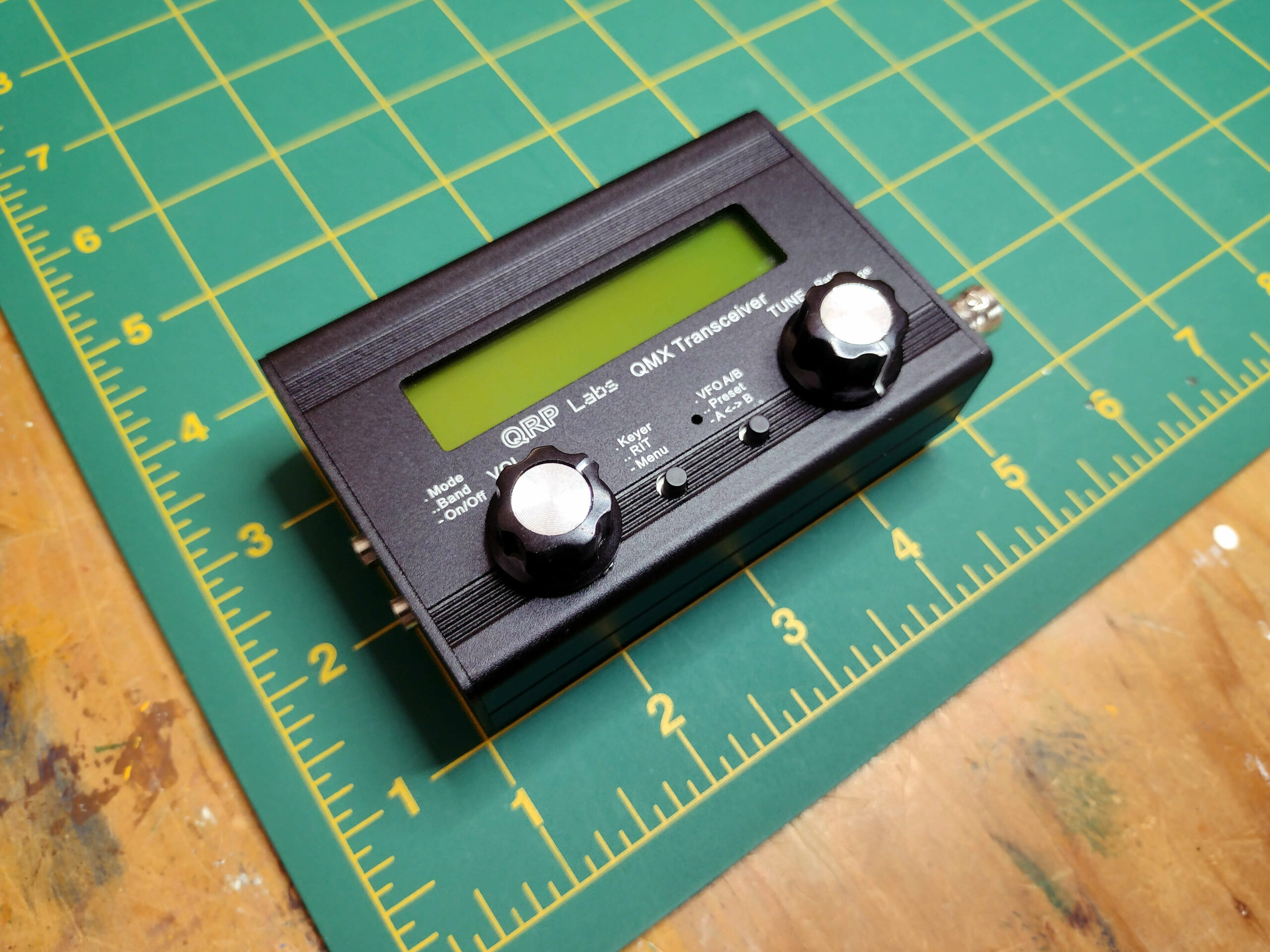
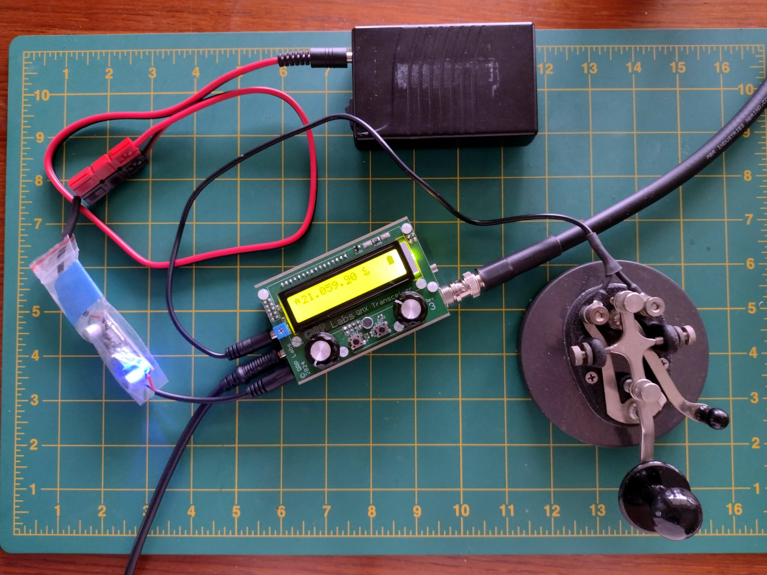
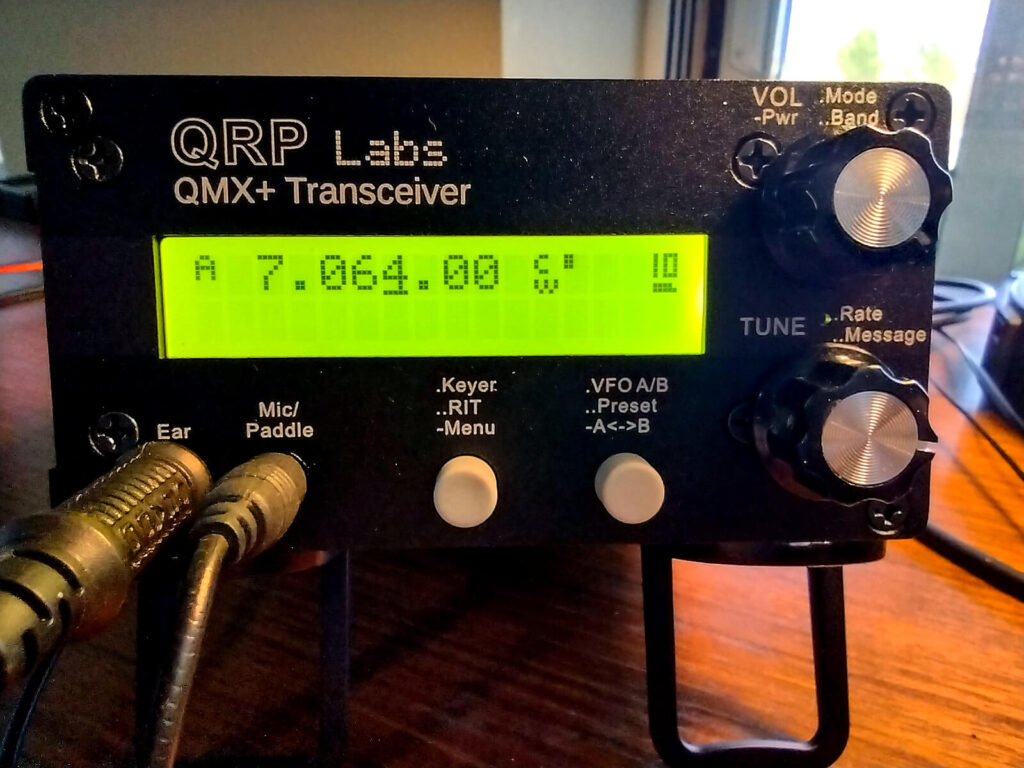
My just finished QMX+ by QRP Labs is a 11 band multi-mode transceiver that I built from their kit. Full details here. Pictured below is the result of the “smoke test.” Success on first power up!

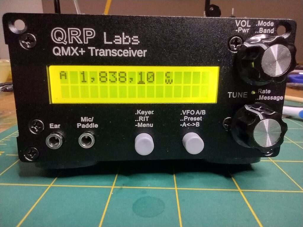
Some time ago, I built the little brother, the more compact QMX successfully from a kit. That 5 band version has been delightful in practice, but didn’t have all my choices of bands. It was the “high band” version with 20m-10m. I wanted to add at least 40M. The QMX+ offers that and more. So, after the smoke test failed to produce smoke, it was time to adjust the display (tone down those boxes) and try 40m. Contacts from my Central Florida home to Indiana and Rhode Island happened in the first 10 minutes. Later in the day, after 20m opened, I made contacts in CA, CT and elsewhere.

Next, was walking through the myriad of settings. Most of all, I tweaked the CW Filters and AGC to my liking. A couple of days into using it, I’m very pleased. It seems a bit more sensitive than its predecessor in that I’m more easily hearing stations in CA and OR. This radio is capable of some DiGi modes, operating as a WSPR beacon, and newly available SSB. My own interest is strictly CW, so I have no comments about the other modes.

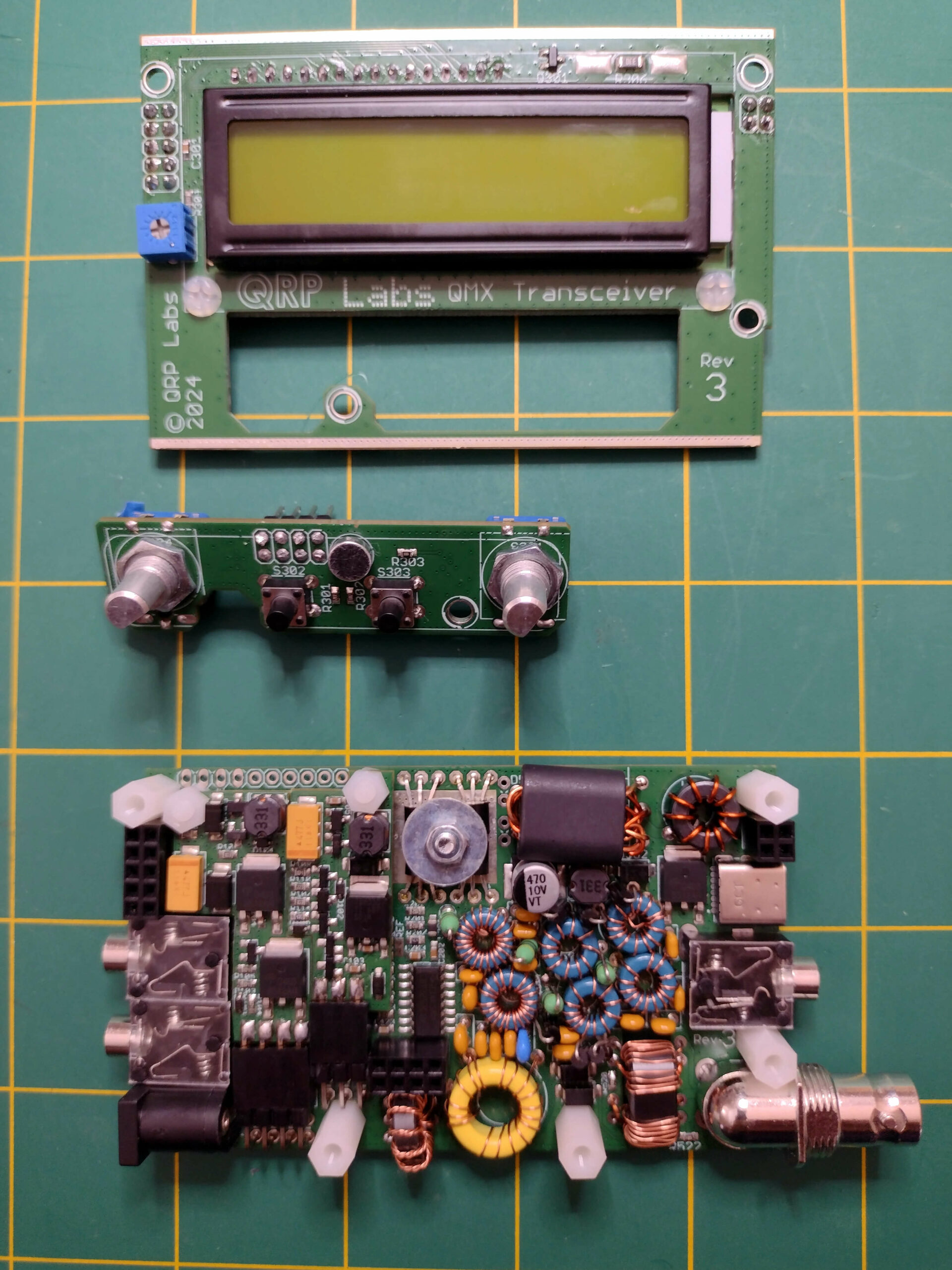
For anyone considering building these kits, I’ll suggest some soldering experience to start. The radios are somewhat difficult because of parts size (small) and density (very). The QMX is more challenging than the QMX+ because of multiple layers in a small case. The QMX+ uses a single larger board in a larger case.

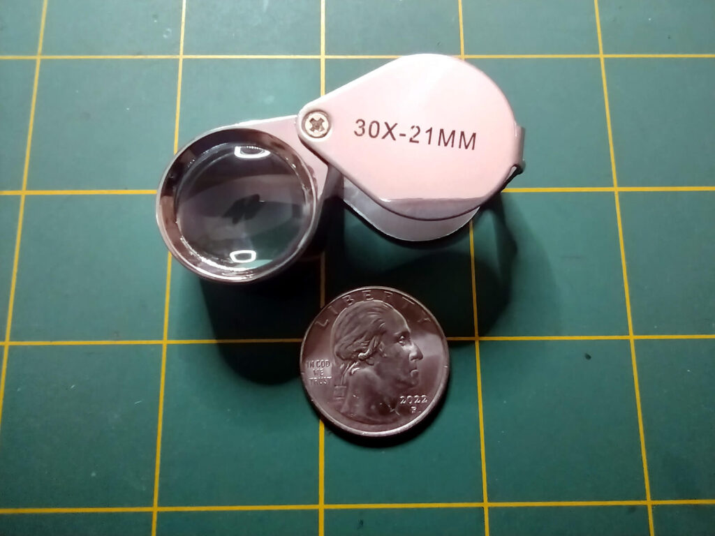
Careful work, with no rush, worked well for me. ABSOLUTELY REQUIRED is careful inspection of every joint with a jeweler’s loupe. Smoke usually is the result of unwanted solder bridges. Use the loupe!

For the record, here are power measurements that I have for this radio.

BandFreq (MHz)Watts
160m1.8385.81
80m3.5735.16
60m5.3584.62
40m7.0744.25
30m10.1365.19
20m14.0373.88
17m18.1042.83
15m21.0944.82
12m24.9243.20
10m28.1244.57
6m50.3133.25

This power distribution looks very similar to others in the QRP Labs series of transceivers. Yes, I would like 20m to be a bit better and might mess with the filter torroids to see if I can bump that a bit. Yet, as it is, I don’t think there’s much difference between 3.9 watts and 5 watts. The little brother QMX has reached Alaska and mid-Germany from central Florida with very similar power figures.

Filed Under: QMX+, radio

FT8

September 6, 2024 by Bob Easton Leave a Comment

So then he says, Let me show you my logbook. It was all FT8!

Nuff said. Because you can’t really say anything on FT8.

jason VE5REV responds: Like callsigns & signal reports? Can we exchange that information with FT8? Can we see propagation patterns with minimal power?? Can we use it when other modes won’t work due to bad band conditions???

Filed Under: radio

QMX – High band version – kit built

August 2, 2024 by Bob Easton Leave a Comment

Introduction

The QMX is a tiny little multiband, multimode, software defined transceiver, from QRP Labs, that runs at QRP power, roughly 5 watts output. Mine is the “High Band” version covering 6 bands from 20 meters through 10 meters. While designed for CW, various digital modes, and SSB, my interest is (you guessed it) CW.

Mine is kit built. I like building things, and building allowed me to acquire a working QMX several months earlier than waiting for an assembled version.

This radio is one version of a series designed by Hans Summers, G0UPL / AF7BF. I am most impressed by how compactly it is packaged. The parts are packed in so densely that successful assembly requires sharp vision, tiny soldering iron tips, and a jewelers loupe. Click on any of the images and then click again to see how dense things are. My successful assembly came by working in small steps and inspecting constantly with that loupe.

Rather than writing more about the technical details of this radio, you might want to read Hans’ own description of how he developed it, a fascinating read for those who like evolution stories.

Assembly done – Let’s start testing

Jul 12, 2024 – At first, I thought it wasn’t getting power correctly.

Yes, the instructions say that when first powered connected PC sees it as a thumb drive.  It also says there is nothing displayed. Yet, somehow I still expected ~some~ sign of life and saw none … other than the bench power supply showing about 1/8 A power draw. (I had it set for 7 vDC and .250 A)  I also have an inline voltage regulator set for 7 volts. It is extra protection to avoid voltages over 12.0, but set to 7 for initial testing.

Look closer! Yes, there is a drive named “QMX” on the PC. Drag the firmware file, 1_00_020.QMX to that drive. Drop power. Power up again and be greeted by “Initializing EPROM,” and other messages. Voila! It works without emitting smoke.

Next, CONFIGURE and test …

Jul 13 – 2024 – First RX tests: After a round of thunderstorms, I connected the HS20 antenna and listened on 20M for a while. This little rig sounds ~almost~ as good as the TR-45L, but has only one CW filter*, 300Hz, which is a reasonable choice. Its audio is FAR better than the (tr)uSDX with enough amplitude that I don’t need the follow-on audio amp, and no unexpected squealing so far.

*update: More filtering options appear in firmware version 23.

So far, so good. Let’s move up to “normal” input power, 11.7v.

BandPower outputPower drawn
20M – 14Mhz4.06 watts0.582 A
17M – 18 Mhz5.61 watts0.797 A
15M – 21 Mhz5.64 watts0.903 A
12M – 24 Mhz3.93 watts0.743 A
11M – 27 Mhz4.05 watts0.772 A
10M – 28 Mhz3.63 watts0.718 A

Jul 14, 2024 – First quick TX tests (key down for 2 seconds) RF power output was with about 11.7v from a Talentcell battery, RF output goes to my QRPoMeter SWR/PWR meter, then to a dummy load. Power drawn was measured from a bench power supply.

On the air: As of Jul 31, 2024 the QMX has enabled quite a few POTA QSOs. I’m pleased with its performance and use it for those bands the TR-45L doesn’t cover.

Update: Oct 18, 2024 – Dozens of QSOs have flowed through this little radio. Yesterday, it helped drive the fun-o-meter way above max. That came from a QSO with Paul Butzi, W7PFB out in the woods in Washington state. I parked on his frequency until I started hearing very faint CW. The usual advice is to avoid trying to contact until you’re absolutely certain of 100% copy. I broke that rule, at the 99 and 44/100s mark. (Oldsters will understand the reference.) Thanks to Paul’s sharp ears, we made it work at the 229 RST level. Thanks Paul!
[fun-o-meter image “borrowed” from Paul’s QRZ page.]

Overall, the radio is a joy to use. Hans, the designer, developed a user interface that is very easy to manage, and the radio has the sensitivity and audio characteristics that obviously perform well for weak signal work. As much as people praise the TR-45L for excellent audio, I enjoy the QMX audio more. It seems to have a better SNR than the TR-45L, and recent filter updates have let me move zero-beat and sidetone frequencies to something more pleasant to my hearing.

Next… AK and HI.

Filed Under: QMX, radio

T41-EP SDT “Pop-Pop” (3 of ?)

July 20, 2024 by Bob Easton Leave a Comment

When we last visited this radio, it was almost complete. That’s when I decided to switch out the power amplifier. The “-EP” in the name means “Experimental Platform.” Let’s experiment. The reason is because of reports of poor power output on higher bands due to the original power amplifier using transistors with a very steep output falloff above 20 Mhz. A newer power amp has a much flatter frequency response at 20 watts output. (I only want 5, but will appreciate the extra headroom.)

The semi-kit by K9HZ Bill Schmidt arrives as a PCB (Printed Circuit Board), a few semiconductors, a few transformer cores, some wire, and a BOM (Bill Of Material) for the rest of the parts. Almost all of the parts were SMD (Surface Mount Devices), giving me the opportunity to learn a new skill. 🙂 Despite needing a very good magnifying glass and a jeweler’s loupe, construction went very well.

So did initial power testing. The fun came along at the next stage, when the “bias” potentiometers are adjusted to produce the correct current flow through each of the power transistors. For that, the amp needed a signal voltage from the transceiver. So, I mounted it in the case and hooked up power.

A very quick “POP-POP” was the response on flipping the rig’s power switch. Puffs of smoke from new holes in the power transistors floated up. All electronic devices are powered by smoke and once you let the smoke out, they no longer work. ;{

What the???? User error, of course. Wrong polarity power. I tried using a new battery, a new LiFePO4. It is a very nice battery that will serve well as a base station power source. My mistake was NOT making up new power cables, but using a couple that were in the box. Hey, these two fit together. I blithely went ahead without realizing that using them in series, instead of alone, produced a polarity reversal. Stupid error! … POP-POP and along with it lesser POPs and PFFFTs inside the mostly complete T41.

As I write this, I don’t know the extent of the collateral damage. After replacing a few parts on the power board, the rest of the T41 does not come to life and there are significant voltage drops on the 5V line. It may be time for an extensive rebuild.
UPDATE: There are enough “anomalies” with the existing build that I’ve decided to rebuild completely using the V12 version of the T41. More function, refined RF specs, and known-good hardware are some of the reasons.

Meanwhile, I can easily rebuild, and correctly test the power amp. It is independent of the main radio and easily rebuilt.

P.S. Safety glasses recommended for first power. In this case, it was under a magnifying glass which stopped the remnants.

Filed Under: radio, T41-EP Transceiver

T41-EP SDT (2 of ??)

May 3, 2024 by Bob Easton Leave a Comment

Construction is well on its way. All the boards are built and the transmitter has passed an important milestone. First a look at the assembly which currently consists of three panels.

On the left is the back panel which currently is home for the 20 watt Power Amplifier board and its boost supply. The middle is the base panel which is home for 5 boards, itemized shortly. The panel on the right is the front panel which accommodates the display, four encoders and an array of pushbutton switches.

photo of the 3 main panels

Back panel

The 20W power amplifier board is the V10 original. It is claimed to be able to produce 20 watts power output across the various bands, using 4 each IRF510 transistors. For this, it also needs voltage higher than the 12 vDC used throughout the rest of the rig. That smaller board is a buck convertor that bucks 12 vDC up to 25 vDC.

Since ordering this kit, I’ve learned that the transistors used in this amplifier have a very steep frequency efficiency falloff that reduces power in the 10M band to something notably less than 5 watts. I don’t care for 20 watts across all bands, but really do want at least 5. So…. there’s another power amplifier waiting in the wings, and it is the reason for that extra open space in the back panel. It will be the subject of another post where Bob learns to handle small SMD components.

Base panel

The 5 boards attached to the base are, from the bottom of the picture to the top:

  • the 12 vDC power supply
  • the QSD, Quadrature Sampling Detector, board where RF signals are prepared for digital signal processing.
  • the Main board which holds digital signal filters, the little Tiny 41 microcontroller which handles all the signal processing, system configuration details, and menu system. This board also houses interfaces for the display, encoders and pushbutton grid, along with some audio processing
  • the Exciter board produces phase shift and SSB, Single Side Band, modulation
  • lastly a filter board includes all the pesky toroids (aka torroids, or toeroids) for RF Low Pass and Band Pass filtering

All of these functions are concisely explained in Al and Jack’s book: Software Defined Radio Transceiver: Theory and Construction of the T41-ep Amateur Radio SDT. About 500 pages which include a deep drive in Digital Signal Processing.

Note: there is now a 3rd version, which adds information for V12, version 12, of this radio.

Front panel

Self explanatory, a display board, 4 encoders, 16 pushbuttons and various other connectors.

Milestone – PA biasing

Even though I intend to replace the V10 Power Amplifier with another, I decided to complete the initialization, or biasing, of this amplifier. Maybe it can be used elsewhere sometime. The process is simple, and avoids smoke and explosions if each of the 4 blue potentiometers are first set to their lowest values (many turns counter-clockwise).

Then, an ammeter is placed inline with a 12 vDC power source and power is applied. The desired result is a base line of 50-55 mA for the board. One by one the blue potentiometers are turned up (clockwise) until the power drawn increases 200 mA for each IRF510 transistor. The end result is a current draw of about 850 mA and no smoke. Success. Done.

BTW, the finned aluminum heatsink, with no fan, reaches about 140 degrees F.

photo of the bias adjustment setup

Next …

A whole bunch of interconnects, software loading, and various adjustment / alignment processes.

photo of cables, knobs, jacks, etc.
a whole lot of jumpin’ goin on

Filed Under: radio, T41-EP Transceiver

T41-EP SDT (1 of ??)

May 1, 2024 by Bob Easton Leave a Comment

The T41-EP is a Software Defined Transceiver designed by Albert F. Peter, AC8GY and Jack Purdum, W8TEE. The “T41” part of the designation comes from the fact that it uses the Teensie 4.1 microprocessor for software processing. The “EP” part of the designation means “Experimental Platform.” I started building Version 10 of the radio a couple of months ago, while Jack and Albert are now well off into version 12. Experimental — evolving.

The 4SQRP version of the T41-EP uses a 5″ LCD and enough front panel controls that one doesn’t have to be constantly digging through menus. That grid of buttons on the right gives instant access to many menu pages.

The picture is from the T41 site, not my build.

My interest is not the 20W capability, but the 15M, 12M, 10M capability. I’ll strick to QRP power levels, but want the rig for the bands. Yes, I have those bands with the “quirky Lil Orange” (tr)uSDX, but I trust the T41 will have more pleasing audio quality, and much easier operation.

My T41-EP

While the designers create circuits, PCB layouts and such, it is up to builders to either collect their own parts or find groups that are collecting parts for sale. One such group is the Four State QRP Group, 4SQRP, located in the Ozarks region of the U.S. A little over a year ago, they began a kitting operation to both promote the T41 and as a fund raiser for their club attending the OzarkCon ham radio conference. One interesting aspect of their sourcing is the provision of Printed Circuit Boards (PCBs) that already have the tiny Surface Mount Devices (SMDs) installed. Buyers are relieved of needing to acquire SMD assembly techniques. It was my very good fortune to snag a kit near the tail end of their run, which I think was 150 units plus a few betas. It arrived a few months ago and has not yet self-assembled.

My first job was making a “jig” to hold circuit boards. I think there are 7 or 8 in the kit. Instead of buying a fancy-looking collection of plastic, I wandered out to my woodworking shop, picked up a 2×2 cutoff, cut a very accurate kerf with my kerfing plane, and cut it into 2 pieces. Done!!! no waiting for Amazon.

The first assembly task is the power supply regulation board. It was an easy way to start and is now done and tested. AOK!

The assembly manual, about 120 pages, is concise and includes circuit diagrams, bills of materials, suggested build sequences, and in some cases test procedures.

A more extensive document, Software Defined Radio Transceiver: Theory and Construction of the T41-ep Amateur Radio SDT, is a 497 page book by the designers, and is a full fledged tutorial on digital signal processing using the T41 radio as the basis. It too holds extensive build and test advice.

Filed Under: radio, T41-EP Transceiver

  • Page 1
  • Page 2
  • Go to Next Page »

Primary Sidebar

Solar-Terrestrial Data

Solar Ham

find the latest solar weather conditions

What’s happening NOW?

Recent Posts

  • QMX+ First run
  • Yet another CW tool from Mike and Becky
  • New QSO Finder tool for CW operators
  • CW Learning Forever
  • My fortune in a cookie

Copyright © 2025 · Bob Easton · N4REE