Let’s make this tool famous!
Looking for a simple QSO … or a ragchew … or a code buddy … or an SKCC exchange? There are a variety of places to find these kinds of QSOs, but usually for only one type of exchange.
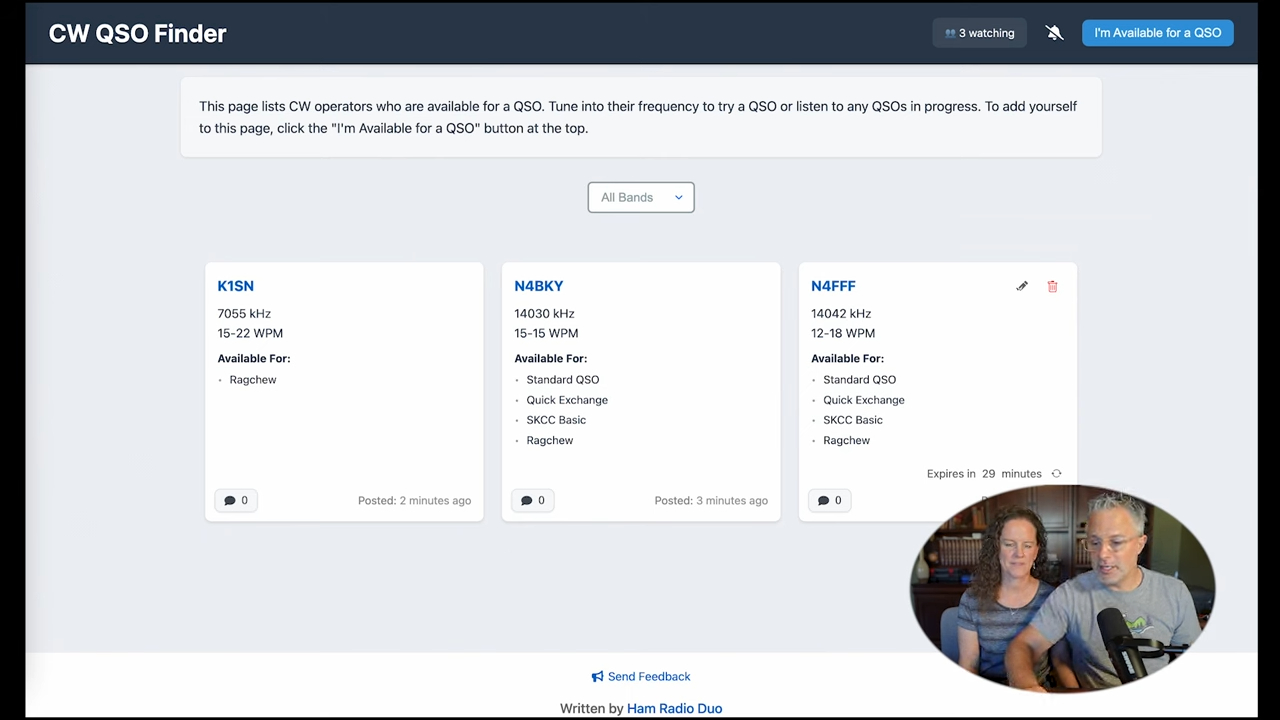
Now, there’s a QSO finder that is highly flexible and fabulous for extemporaneous QSOs of various types. Becky N4BKY and Michael N4FFF have just launched CW QSO Finder, a new tool to help you find the kind of QSO you want. Their intro video tells you all about it.
Several other tools exist, but here’s why I think we all should make this one famous:
- Spontaneity: Use it right now, when you want it. No need to plan ahead, or sign up for some list that gets updated once in a while and hidden in a box in the back hallway of a website.
- Handles a variety of conversation types. POTA/SOTA and SKCC have some very useful tools, but are limited to those respective audiences.
- Modern and intuitive: Each availability spot appears as a card that clearly shows the operator’s QSO interests.
- Dynamic: Each card lives for 30 minutes, shows when it was posted, is easily modified by its author, and can accept comments from others.
- BTW… the “off page” link next to the callsign leads to that person’s QRZ page, very handy for learning more about that CW partner.