• Skip to primary navigation
  • Skip to main content
  • Skip to primary sidebar
  • Skip to footer

Bob Easton

Chocolate powered woodworking

  • Home
  • Grinling Gibbons Tour

Bob Easton

Chinese Seal Box

October 31, 2016 by Bob Easton 8 Comments

the mark of the Chinese sealA thin photo of Chinese seal box - closed
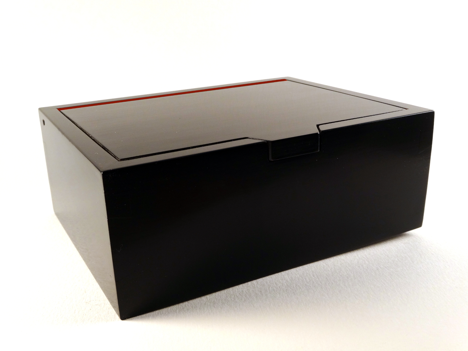
sliver of red teases from the back edge of the lid, like the sole of a Christian Louboutin shoe.

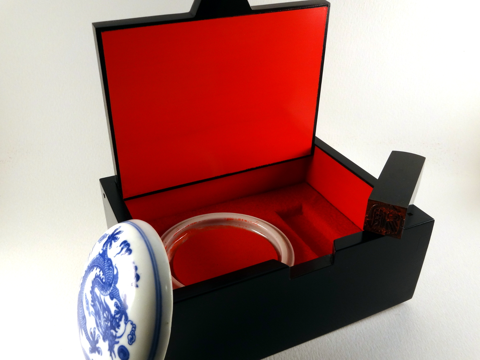
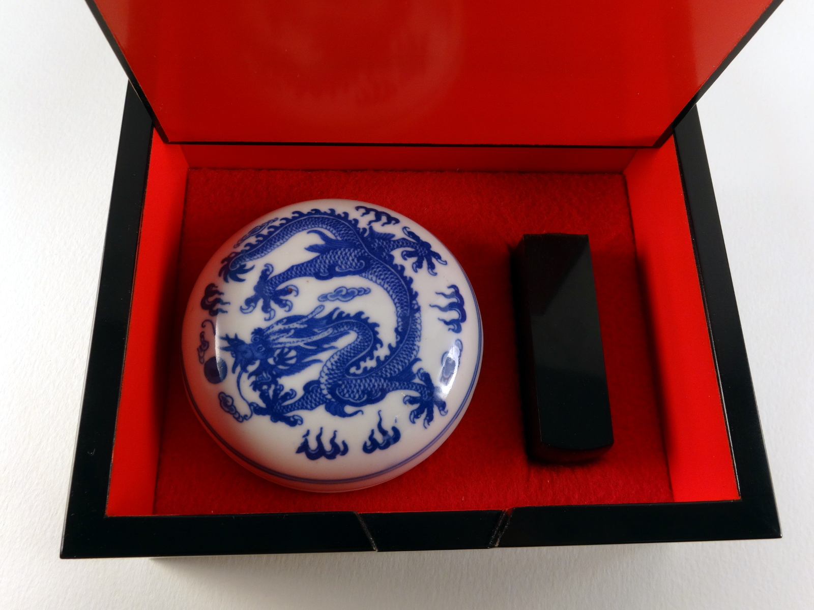
Eva, my wife, is a linguist and language fanatic. One of her language partners, who lives near Beijing, bestowed on her an honorary Chinese name. It is the pseudonym of a premier Chinese poet he admires, Yi’an Jushi. A reasonable translation is “Amiable Calm.” He also sent a Chinese “seal,” a stamp that embodies the two characters of the name in a traditional form.

Something as nice as that Chinese seal deserves a nice box to live in. And of course, it wants to have a traditional black and red Chinese lacquer finish.

Cherry with mitered dovetails and flip lid,
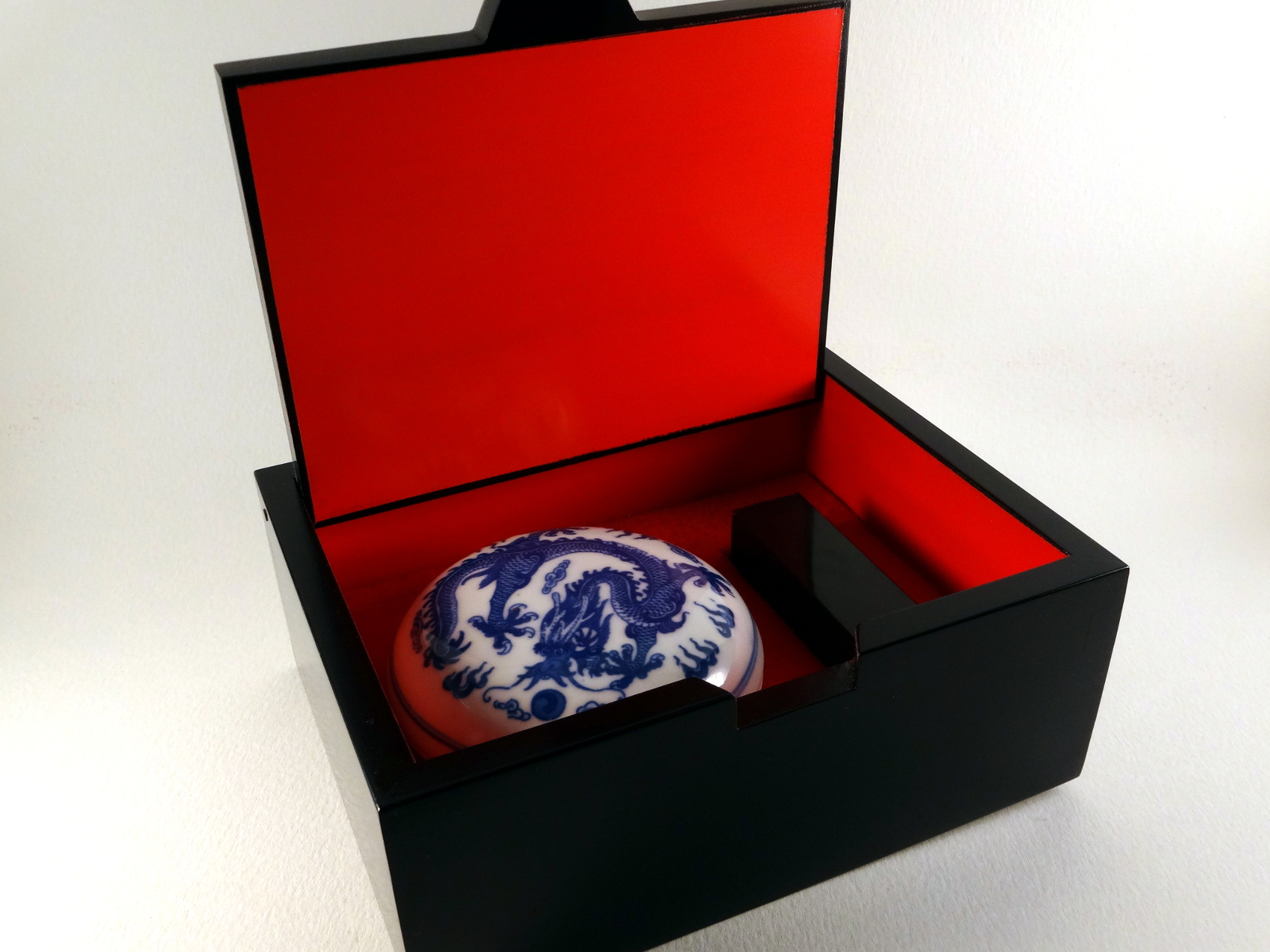
“French fitted” interior,
Dimensions: 6 3/4 inches (L), 5 1/4 inches (W), 2 5/8 inch deep,
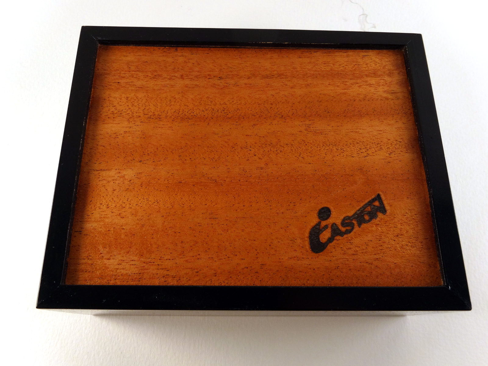
Bottom: 1/8 inch mahogany,
Finish: Red lacquer interior, Black lacquer exterior.

This box includes a “French fitted” interior to hold a seal and dish containing an ink pad.

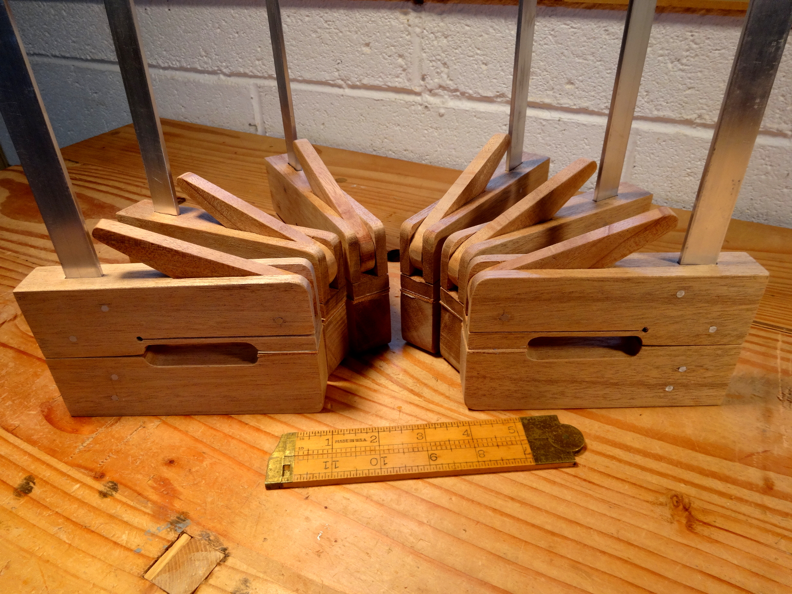
The mitered dovetailed corner, as shown in an older post, offers the traditional dovetail join, but with miters on the ends which provide a much nicer finished appearance when seen from the top or bottom of the box. The miters also allow the groove for the floor to be routed straight through but also be concealed.

Unlike my other boxes, there’s no external carving on this box. The only thing that can be considered carving is hollowing out some spaces in an interior block to create the French fitting. By the way, the fabric for the fitting is simple red felt attached with rubber cement adhesive. The porcelain dish is an “upgrade” from the plastic box that originally held the stamp pad.

Beware! – Lacquer Lessons

It’s called “tuition.”

Finishing this box was an adventure. I really wanted a lacquer finish, and eventually got one. The first challenge was finding actual lacquer. Thanks (mostly) to California regulators, we no longer have true, hard, extremely durable lacquer made of nitrocellulose. There’s a close substitute in the auto industry, but I wasn’t ready to buy auto finish in gallon quantities, and I don’t have a professional spray booth to use it in. I settled for some rattle-can pseudo lacquers meant for model cars. The one trait these pseudo lacquers share with the real stuff is sensitivity to humidity … and New York summers have plenty of that. I was constantly checking weather charts to find afternoons with less than 50% humidity.

The bigger lessons weren’t about humidity, but…

  • As hard as lacquer seems, it is still susceptible until very well cured. I painted the inside, red, parts first and then the black outside. (Yes, I used the usual blue painter’s tape.)  After painting both, I let the parts sit for about a week. I parked the lid, which at most weigh no more than two ounces on a group of painters’ points, those nice little plastic pyramids. At the time, the red paint was probably a week old. Coming back at the end of week resting on the points, I found dimples in the red finish. Most would “rub out,” but there were other reasons for redoing the red. …
  • Somewhere way down the page about 3M’s blue painters’ tape is mention that the adhesive in that tape sometimes interacts with lacquer. I found out after removing blue tape masking and finding a residue that could not be removed. None of the magic potions I tried touched the stuff. Scraping was the only thing that worked, and of course did enough damage to require re-painting the red. 3M’s suggested prevention is to use their Green painters’ tape, product #2060, and to remove tape as quickly as possible. The #2060 product recommends 3 days max.

After those lessons, completing the finish was a matter of hand rubbing. I found that either of these processes worked equally well:

  • let the last coat cure until the distinctive lacquer smell disappears (about 1 week)
  • gently sand with 400 to remove nibs
  • work through the abrasive pads 500, 1000, 2000, 4000
  • wax and buff

OR…

  • let the last coat cure until the distinctive lacquer smell disappears (about 1 week)
  • gently sand with 400 to remove nibs
  • rub with a pumice slurry, down to an even satin sheen (abt 500 grit)
  • rub with rottenstone slurry until shiny (abt 2000 grit)
  • buff clean
  • wax and buff

Click any of these images for a larger view.

photo of Chinese seal box - closed photo of the Chinese seal box - lid open photo of the Chinese seal box - open and in use photo of inside of Chinese seal box photo of french fitting inside Chinese seal box bottom of Chinese seal box

This is Box #18

Filed Under: Boxmaking, Woodworking

Taming Roy’s Jigsaw Scroll Saw

September 22, 2016 by Bob Easton 17 Comments

Clackety-clackety-clackety thunk-clackety-thunk. What a contraption! Roy says, “Won’t the kids be proud!” Well, maybe … if they don’t run off scared.

drawing from a magazine article
drawing borrowed from Popular Woodworking magazine. October 2000
A little postage stamp sized illustration, and a few scant paragraphs, describe a jigsaw in Roy Underhill’s treadle lathe article for Popular Woodworking (October 2000). When I built my lathe, while not to Roy’s plans, I filed the idea away because a jigsaw / scroll-saw would be a very useful thing to have for certain carving projects.

Well, it’s time. I want one. Actually, I want a scroll saw, not a jigsaw. The distinction I make is that Roy’s jigsaw was designed for relatively coarse coping saw blades. My first want is for cutting out blanks for woodcarvings, blanks that can be 1″ thick or more. Coping saw blades are OK for this. Yet, I also want to do finer work with tighter turns than one can get with coping saw blades. There’s where fine scroll saw blades are needed.

Roy provided just enough information to build a saw that’s just about works. I had just enough scrap wood to knock together a “semi-beautiful” prototype made of 4 different kinds of lumber. Even as a prototype, I changed a few things from Roy’s drawing:

  • My lathe center is a higher height from the bed than Roy’s. So, I extended the dimensions for the arm pivot points accordingly.
  • I made a different crank. Roy’s plan suggest a bent crank that replaces the lathe’s spindle. Having long ago discovered the town smithy left for lower taxes elsewhere, I modernized my lathe spindle to use standard 1″x8 lathe chucks. I thought long and hard about the crank. Roy’s plans called for a 1/2″ crank pin with a 1″ throw from center. photo of original crankReluctant to go find a machinist (a title I once had in the USAF), or to beg a favor from my Hoosier acquaintance Roger Davis, I decided to “adapt.” I think that’s French for “make something work.” I found a 3″ steel faceplate that had a circle of 4 holes that are 1/4″ in from the edge.

    Perfect! Drill 2 of those out to 1/2″ and use 1/2″ bolts and nuts. One bolt, star washer and nut points away from the plate and becomes the crank pin. A partner bolt, star washer and nut points toward the headstock and is a counterweight. The result a crank with a 1-1/4″ throw, 1/4″ more than plan, but what’s a 25% difference among friends!? (more on that later)
  • The tiny drawing didn’t show details for the blade mounts, but the article did suggest hacksawing the ends off of a coping saw and using those. I tried something similar, by using clamp style ends from a jeweler’s saw. That approach would be good for non-pinned blades. It turns out they don’t hold well enough. So, I replaced them with excellent brass saw pins that I used for my turning saw. They’re are Gramercy Tools Turning Saw Pins from Tools for Working Wood. These pins are for pin-end blades and are beautiful when compared to any coping saw blade holder.
  • I made my crank link from oak and fitted it with ball bearings left over from building the lathe, and a single piece of iron strap to attach it to the lower arm.

My first reaction to using it was to call it “the contraption.” The action was very wobbly. It clattered around with a LOT of thumping and rattling. The blade, being at the ends of long arms set on moderately imprecise bearing points, moved with a lot of “dancing” action, much like a very wide and jerky do-si-do. It worked, but as my wife says “it looks like a great exercise machine.”

Yet, it does cut, if the turnbuckle is properly tensioned and locked and all the rest of the connections made secure enough to not rattle apart. My first trials were with box-store coping saw blades and were promising enough to encourage me to see if scroll saw blades would work.

Scroll saw? Yes, but… It needs some adjustments, erm… improvements. Let’s set aside the first version and build Mark II. It is very similar, but refined in several ways. And, it’s completely constructed from oak, rather than 4 different woods used for the proof of concept version. Two pics: from the back (note the trunbuckle and lock nut), and from the front (with an adjustable arm guide).
photo of scroll saw from the backphoto of scroll saw from the front

  • The pivot points of the arms were changed so that the arm baselines are parallel when using my preferred blade, in this case 5 ” scroll saw. Coping saw blades will still work, but the motion is now optimized for scroll saw blades. I made sure these were sized using the Gramercy pins. Hint: If you do this, just lay all the parts out on a large piece of paper and measure. You don’t need precise SketchUp drawings.
  • photo showing the crank linkA new crank link embraces both sides of the lower saw arm. The Mark I version attached to only one side of the arm and contributed to the dancing action. Roy had this right. I took a shortcut with Mark I and learned from it. The new crank link is the same thickness as the lower arm. It houses a pair of bearings and has straps on both sides, providing much better lower arm stability. Not wanting to simply attach it with a screw that will eventually chew through the wood of the lower arm, the link is attached to the lower arm with a length of 3/16″ OD brass tubing. Inside that tubing is a 1/8″ screw and retaining nut that does nothing more than keep the tube in place.
  • The distance between the end of the crank link and the bottom arm was tightened up. Reducing that distance allowed the table to be lowered 5/8″ and allows cutting material about 1-1/4″  thick with scroll saw blades, thicker with coping saw blades.
  • The eye-bolts on the first version were too close together, leaving too little room for enough turnbuckle adjustment. Sinking the eyes half their diameter into the arms affords plenty of adjustment.
  • The table position of the Mark I didn’t accommodate a 1″ work piece. I want to be able to cut blanks for woodcarvings that are 1″ thick (or more sometimes). A test with basswood did show very nice “dimpling” where the brass pin from the upper arm banged the top of the board. Adjusting the crank link clearance and changing table height allows for sawing thicker material.
  • The Mark I had bronze bushings only in the arms, but not in the tower they swing from. It didn’t take long to realize the inaccuracy of these pivot points was contributing a lot to the clatter and dancing. Mark II has bushings in the arms and the tower. Better! Much less do-si-do, and I expect much less wear over time.
  • Being eager to see if it works, I used 1/2″ x 2″ bolts and nuts as pivot axles on the Mark I. They worked, but contributed to the rattling and clattering. Those bolts were replaced with 1/2″ bar stock and cotter pins. This alone makes a huge difference. In the case of arms with bushings and the tower with bushings, “waggle” measured at the end of an arm is about 1/8 – 3/16″ with a bar axle. It was 3/4″ with a bolt axle – an amazing 5x to 6x difference!
  • photo of drilling using a small levelAll of the bearing points are as plumb as I can make them without a drill press. Careful fitting with a rat-tail file and epoxy got them to acceptable precision. By the way: My method for checking uses a small level. I don’t recall when or where I got it, so can’t recommend where to get one. What makes this one handy are legs that have “V” notches in them. It’s easy to sit the level on a long piece of bar stock and make adjustments as needed. It’s also very handy for hand drilling. I prefer to clamp the work piece vertical and drill horizontally. It’s very easy to be square in the left-right axis that way. For the up-down axis, use the level on the drill bit. The result comes very close to what one gets with a drill press.
  • Even with all of that extra care, there’s still more dancing than I want. The problem comes from the lower arm being nicely fixed near the blade, via the drive crank. It’ doesn’t have room to wobble, if the crank pin is true. However, the top arm has only that pivot point way at the back, allowing the blade end plenty of movement. Tight tensioning of the blade helps control that arm, but not quite enough. My solution is a yoke that can be positioned where needed to guide / tame the upper arm.

    By the way, a lock nut has been added to the turnbuckle. After tensioning a blade, tighten up the lock nut. Otherwise, the motion of the arms will loosen the turnbuckle and the blade will go flying. Yes, safety glasses are a good idea! A note on tension: the tighter the tension, the more friction in the movement. Too tight and the saw won’t operate smoothly. Too loose, and the blade won’t follow a curve smoothly.
  • photo of revised crankIt turns out that the extra 1/4″ throw, from using the easiest place to put the crank pin on the faceplate, means added friction (and energy) at the horizontal inflection points. It takes a lot to keep the motion going through those points. Maybe Roy’s 1″ throw was right?
    So… out comes the 4-jaw chuck and an experiment to reduce the throw back to 1″. A pin set at 1″ offset can’t be held very well in my chuck, but it was enough for a trial. What a HUGE difference!!

    Now, to make a more permanent version…A bolt, or crank pin, can’t be moved in closer on the faceplate, toward the lathe axis, without running into the spindle. So, put the crank pin through another plate. My next step was to create a wooden plate (cherry), and drill a hole for a 1/2″ pin. The pin is epoxied in place with JB Weld. JB Weld sets up in 4-6 hours, giving plenty of time to ensure the pin is square to the faceplate. And yes, I included a bolt facing the wrong way as a counterweight. The crank is well balanced; there’s no vibration from the crank.

photo of 2 sawed out piecesThe pieces in the last photo were practice exercises, in effect the “final exam” for whether the saw can do what I want. The saw passed the exam, but the sawyer needs more practice! The Acanthus leaf is 3/8″ thick basswood, and easily cut. The smaller piece is a dragon’s claw, only a fragment of a much larger carving. It too is basswood, 1″ thick. The blade is extra fine 18 TPI, leaving a very smooth surface.

TAMED!!!  Now, I’m happy. I can cut carving blanks with the detail I want. It is not a saw for very fine fretwork or for cutting wooden clock gears, but it does what I want.

Filed Under: scroll saw, Shopmade, treadle lathe

Six Little Cam Clamps

June 6, 2016 by Bob Easton 6 Comments

photo of 6 handmade cam clamps

My box making work will appreciate these clamps. I’ll see shortly if 6 are enough. They are extremely light weight, have just the right amount of gripping strength (I think), and are quickly adjusted.

Plans and video instruction from Paul Sellers. Paul says these are easy to make and are inexpensive. They are. What he doesn’t say is they take a LOT of steps, which is why most off-the-shelf versions are relatively expensive.

Materials: 4/4 mahogany, aluminum bars 1/8″ x 1″ x 18″, 10 penny nails, bits of leather.


Filed Under: Hand tools, Shopmade

  • « Go to Previous Page
  • Page 1
  • Interim pages omitted …
  • Page 19
  • Page 20
  • Page 21
  • Page 22
  • Page 23
  • Interim pages omitted …
  • Page 128
  • Go to Next Page »

Primary Sidebar

Footer

Recent Posts

  • New Frame Saw / Scroll Saw
  • Lamppost Sign
  • Goodbye PayPal – Goodbye Bob’s eBooks
  • Anarchist’s Workbench is Done
  • Why we keep offcuts…

Categories

  • About
  • Artwork
  • Boatbuilding
  • Boating
  • bowl carving
  • Boxmaking
  • Clocks
  • Drawings
  • eBook
  • etude
  • Eva Too
  • Eva Won
  • Fiddlehead
  • Fiddlehead model
  • Flying
  • frame saw
  • gilding
  • green woodworking
  • Grinling Gibbons
  • Guns
  • Hand tools
  • Humor
  • kerfing plane
  • Lettercarving
  • Mill Creek 13
  • Model building
  • Power tools
  • Rant
  • resawing
  • scroll saw
  • Shopmade
  • sign painting
  • Stonework
  • Swimming
  • Technology
  • The Wall
  • treadle lathe
  • Uncategorized
  • VSD
  • Woodcarving
  • Woodturning
  • Woodworking
  • workbench

Other stuff

  • About
  • Contact
  • Privacy Policy

Copyright ©2024 · Bob Easton · All Rights Reserved