• Skip to primary navigation
  • Skip to main content
  • Skip to primary sidebar
  • Skip to footer

Bob Easton

Chocolate powered woodworking

  • Home
  • Grinling Gibbons Tour

Bob Easton

Regulator Clock – Case Frames – 1

December 5, 2017 by Bob Easton Leave a Comment

Gratitude: Good hide glue

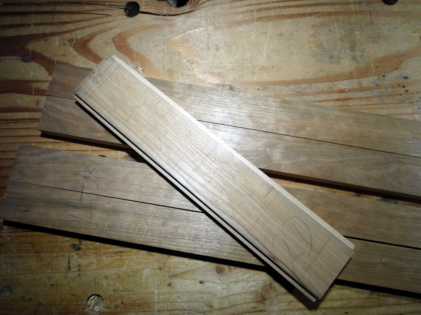
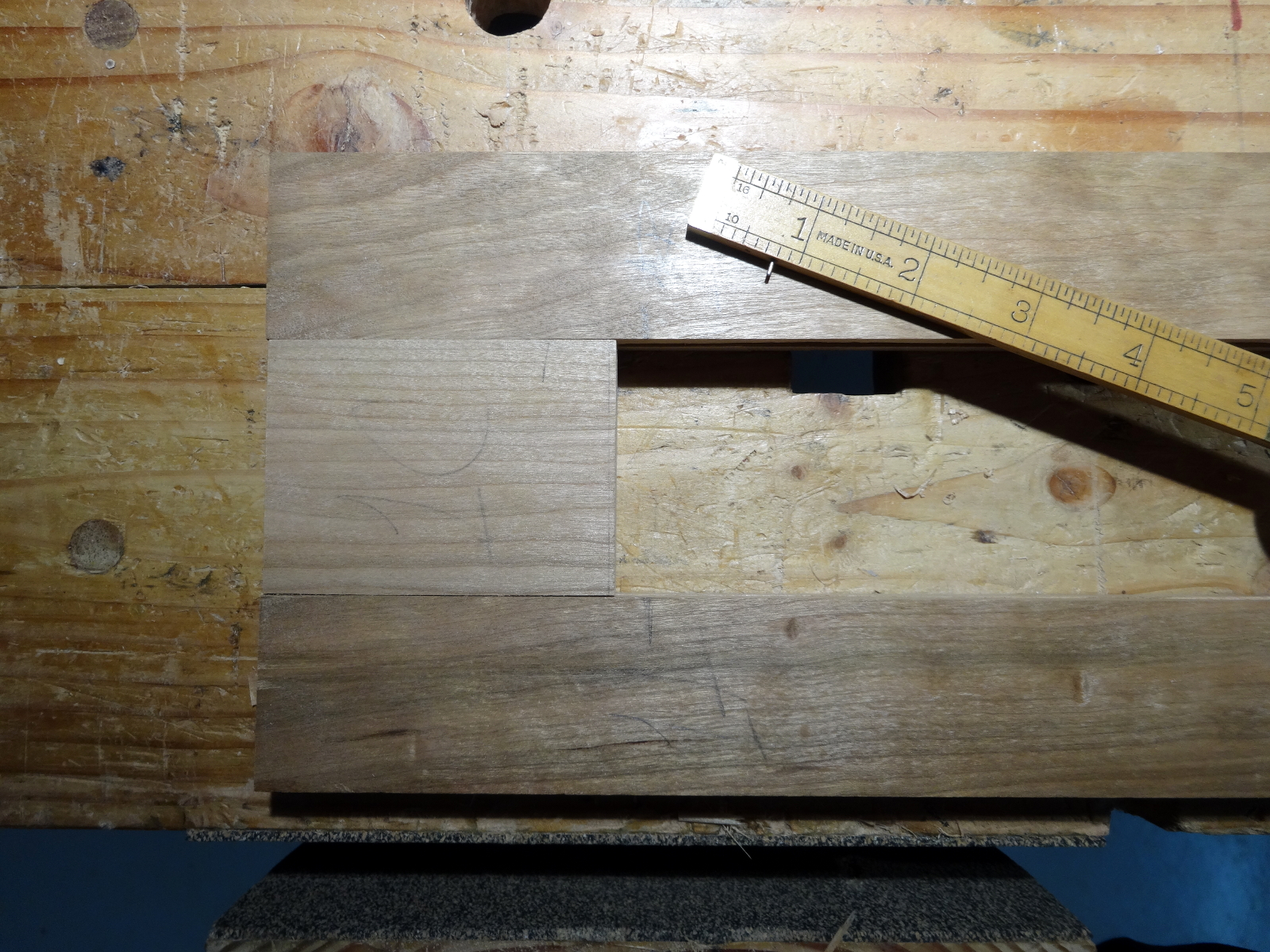
We’ve already seen the top, bottom, and back. The sides and the door are constructed alike; two vertical rails and two stiles. They are joined by simple tongue. and grooves, using the planes acquired recently. My execution ends up with joins that are on the looser side of snug; not quite “self supporting,” but not sloppy either. Put it this way: there’s no danger of parts splitting from hammering the pieces together. The important thing, for me, was getting gap free joins on the show sides of the panels. The step that helped the most was cutting the tongues for the stiles on a longer piece of wood that was then cut to 4 pieces (2 for each side) once the edges were dead straight. Try as I may, my planing still produces a bit of slope-up and slope down at the starts and ends of boards. I sometimes accommodate that by using a board longer than needed and trimming off the slopes. Repeat same for the two stiles (different width) used on the door.

  • photo of side rails and stiles
  • photo of partial side assembly
Photo of tongue and groove break test

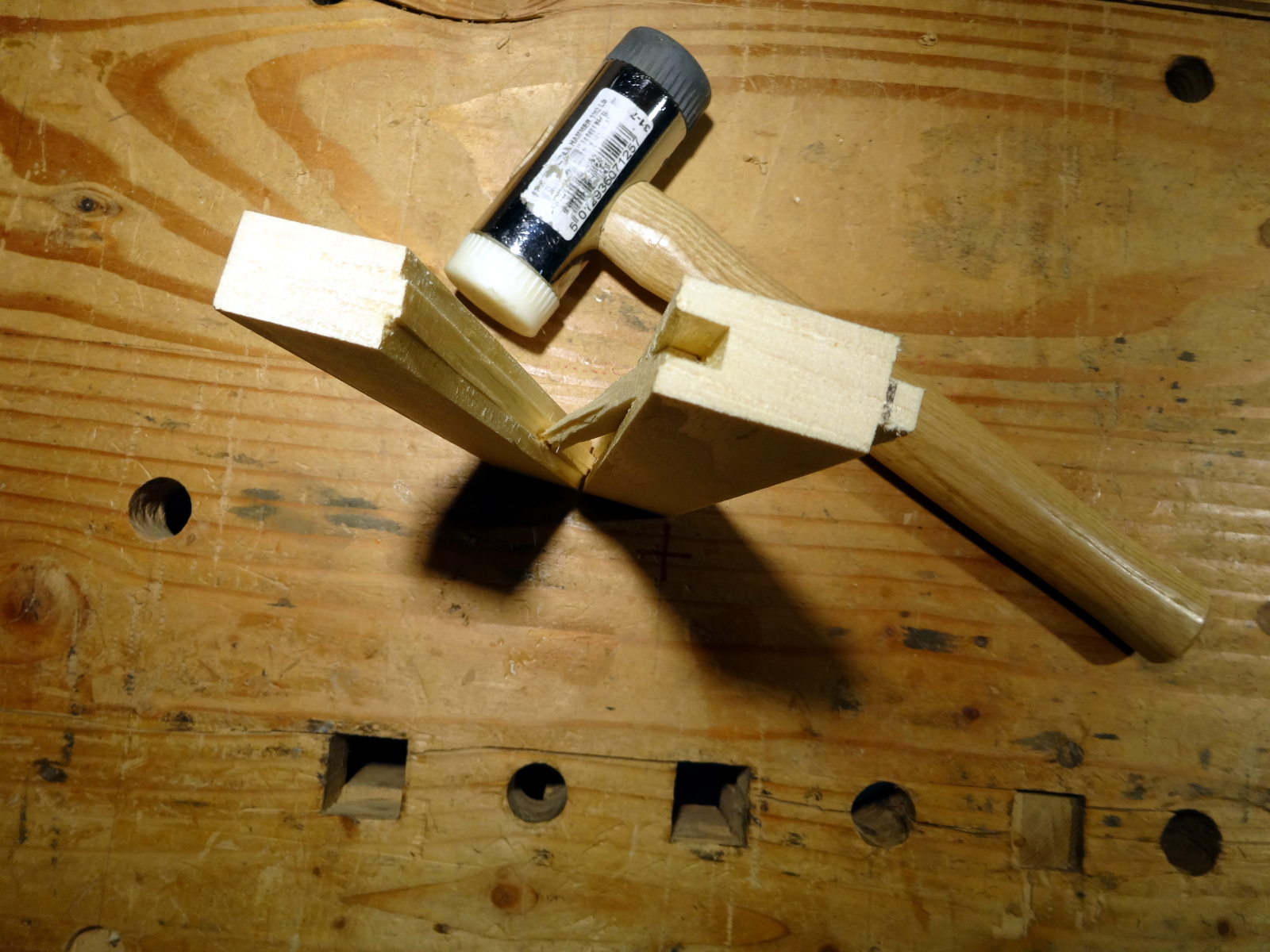
Worrying about how hide glue will hold the slightly loose joinery, I made a test pairing of a couple of sticks of pine … leaving one a bit longer so I could knock it apart later.  My previous use of hide glue has been from 252 strength granules and always had an uncomfortably short open time. This time, I mixed up some 192 strength and gained a wee bit more open time. (Maybe if the shop was by the beach in Costa Rica with 100°F temps?) I applied the glue rather sloppily to only one piece and pressed the joint together in the bench vise for only a few minutes. I then left it sitting in the shop at something less than 60ºF for about 20 hours. When I knocked it apart, I was very pleased to find that almost all of the breakage was in the wood, with almost none exposing raw glue. I’m now confident that careful glue-up will be sufficiently strong.

Other articles in this series…

  • Regulator Clock – Done
  • Regulator Clock – Woodworking completed
  • Regulator Clock – Scratching the frames
  • Regulator Clock – Door Hinged
  • Regulator Clock – Case Dry Fitted
  • Regulator Clock – Jelly Side Down
  • Regulator Clock – Case Frames – 2
  • Regulator Clock – Glass – 2
  • Regulator Clock – Case Frames – 1
  • Regulator Clock – The Works work
  • Regulator Clock – Glass
  • Regulator Clock – Tongue & Groove planes
  • Regulator Clock – Completed Mouldings
  • Regulator Clock – Stick Mouldings
  • Regulator Clock – Plate Mouldings
  • Regulator Clock – Egg and Dart Moulding
  • Regulator Clock – Eat Dessert First
  • Regulator Clock – original description
  • Regulator Clock – Stock Prep
  • Regulator Clock – Plans for Moldings
  • Taming the Rabbet

Filed Under: Clocks, Woodworking

’round tuits

November 18, 2017 by Bob Easton 7 Comments

photo of hand carved round tuitsGratitude: Having so many choices of things to do.

When you get a round tuit, …

cherry, hand-turned, hand carved, finished with common paste wax

Filed Under: Woodcarving, Woodturning

Regulator Clock – The Works work

November 8, 2017 by Bob Easton 7 Comments

Gratitude – clock oil

photo of back board

Some mechanical clocks are regulated by pendulums. Those clocks can’t be wandering around. The pendulum must swing an equal distance to each side of a center line that runs through the escapement. That center line needs to be plumb and fixed so it doesn’t move. This requirement makes the back board the most critical piece of the clock case. Not only does the back board hold the movement and chime rods in place, it also needs to provide a way for hanging the case on the wall and keeping it fixed in place. Here, we see the back side of the backboard.  A through hole on the center line near the top of the board is the single hang point for the case. About two-thirds the way down the line is a slot which fits snugly over a screw head protruding from the wall, keeping the case from wandering.

Keen observers will note two such slots. The first slot is the result of one of my pet peeves: measuring instruments have far too many marks on them, leading to errors. The second slot is the one I’ll actually use.

The board is cherry faced plywood (ouch it hurts to use that word / stuff). It is wide enough to be concerned about movement, so I relented to using plywood. It is drilled with 3 holes along the top edge and 3 along the bottom for fastening the board to the rest of the case. The four larger inset holes are for mounting the clock movement. Insetting whose holes keeps steel nuts from scraping on a wall. The four smaller countersunk holes are for mounting the chime block.

closeup photo of the works and chimes

Only a couple of companies still manufacture mechanical clock movements. This one is by Hermle. It has three trains. Left to right (see the square winding pegs) they are: the hours chimes, the time, and the 1/4 hour chimes. Both chime trains are spring driven. Note the spring holding cylinders behind the winding pegs. The time train is weight driven, providing a steady source of power that does not vary as a spring might. Thus, a well regulated clock.

BTW, the spring for the 1/4 hour chimes has the yeoman’s job and is much heavier than the spring for the hours train. That heavy spring could probably be an alternate power source for when Tesla decides to quit making coal-powered automobiles.

photo of the works being tested - held in a bench vise

In these pictures, the back board is positioned in my bench vise so that it is level across the top, making the center line plumb. The movement is also mounted so that it too is level across the top. …and yes, the clock was running, making the pendulum look off plumb, because it was swinging.

The chimes are copper rods set into an iron block that is positioned so the chime rods are about 1/8 inch from the tips of the hammers when the hammers are “at rest.” A spacer block completes the positioning of the chimes rods.

I set it up this way to test the works, while they are not obscured by the case. This movement has been sitting unused in storage for at least three years. Upon setting it up, the 1/4 hour strike train ran very very slow, taking about 2 seconds to strike a single note. I put the pendulum in its hanger, set the escapement for an even beat and let it run overnight, hoping that some run-in would free up the slow parts. Didn’t happen. Having some clock oil on hand from previous clock work, I sparingly oiled every pivot. That worked. The chimes are now running at full speed and the time train is also running smoothly.

The escapement consists of the pendulum and a pallet bar that controls the turning of the escape wheel. The pallet bar can be adjusted on its shaft to produce the correct action, and that action is noted by a very even beat between the ticks of the pallets striking the escape wheel. This video show the setting is pretty close, maybe not perfect, but close enough for initial testing.

Next, we have the nicely running chimes.

Before long, I’ll take all the pretty stuff off the back board and put it safely aside so I can continue building the rest of the case.

Other articles in this series…

  • Regulator Clock – Done
  • Regulator Clock – Woodworking completed
  • Regulator Clock – Scratching the frames
  • Regulator Clock – Door Hinged
  • Regulator Clock – Case Dry Fitted
  • Regulator Clock – Jelly Side Down
  • Regulator Clock – Case Frames – 2
  • Regulator Clock – Glass – 2
  • Regulator Clock – Case Frames – 1
  • Regulator Clock – The Works work
  • Regulator Clock – Glass
  • Regulator Clock – Tongue & Groove planes
  • Regulator Clock – Completed Mouldings
  • Regulator Clock – Stick Mouldings
  • Regulator Clock – Plate Mouldings
  • Regulator Clock – Egg and Dart Moulding
  • Regulator Clock – Eat Dessert First
  • Regulator Clock – original description
  • Regulator Clock – Stock Prep
  • Regulator Clock – Plans for Moldings
  • Taming the Rabbet

Filed Under: Clocks, Woodworking

  • « Go to Previous Page
  • Page 1
  • Interim pages omitted …
  • Page 14
  • Page 15
  • Page 16
  • Page 17
  • Page 18
  • Interim pages omitted …
  • Page 128
  • Go to Next Page »

Primary Sidebar

Footer

Recent Posts

  • New Frame Saw / Scroll Saw
  • Lamppost Sign
  • Goodbye PayPal – Goodbye Bob’s eBooks
  • Anarchist’s Workbench is Done
  • Why we keep offcuts…

Categories

  • About
  • Artwork
  • Boatbuilding
  • Boating
  • bowl carving
  • Boxmaking
  • Clocks
  • Drawings
  • eBook
  • etude
  • Eva Too
  • Eva Won
  • Fiddlehead
  • Fiddlehead model
  • Flying
  • frame saw
  • gilding
  • green woodworking
  • Grinling Gibbons
  • Guns
  • Hand tools
  • Humor
  • kerfing plane
  • Lettercarving
  • Mill Creek 13
  • Model building
  • Power tools
  • Rant
  • resawing
  • scroll saw
  • Shopmade
  • sign painting
  • Stonework
  • Swimming
  • Technology
  • The Wall
  • treadle lathe
  • Uncategorized
  • VSD
  • Woodcarving
  • Woodturning
  • Woodworking
  • workbench

Other stuff

  • About
  • Contact
  • Privacy Policy

Copyright ©2024 · Bob Easton · All Rights Reserved