Lathe builders in 1805 didn’t know Roger Davis. They’d just have a blacksmith make them a simple crank and be done with it. I didn’t know Roger either when I built my lathe. He saw the blog entry showing the (pathetic) wooden crank I made, in the absence of a blacksmith, and suggested it wouldn’t last long. It didn’t. He then made me one that will never fail. It is solid!
Roger Davis is a fellow Hoosier with the good sense not to move to New York, a frequent visitor to the Sawmill Creek forums, owner of “a very complete machine shop” and self-proclaimed “lack of good sense,” an aerospace engineer by education (Yay Purdue!), former high school teacher (physics, cemistry, algebra), a builder of scientific instrumentation (start to finish) as his paying job, a builder and user of muzzleloaders as one of his hobbies, and variously proficient in gunsmithing, blacksmithing, woodworking hand tools, A&C furniture, cooperage and who knows what else. Bottom line: a generously good guy.
So, why am I telling you all of this? Josh, from the previous post, wanted more information about the machined crank, as did Matt in the comments on the post about Stephen Shepherd’s kit of parts.
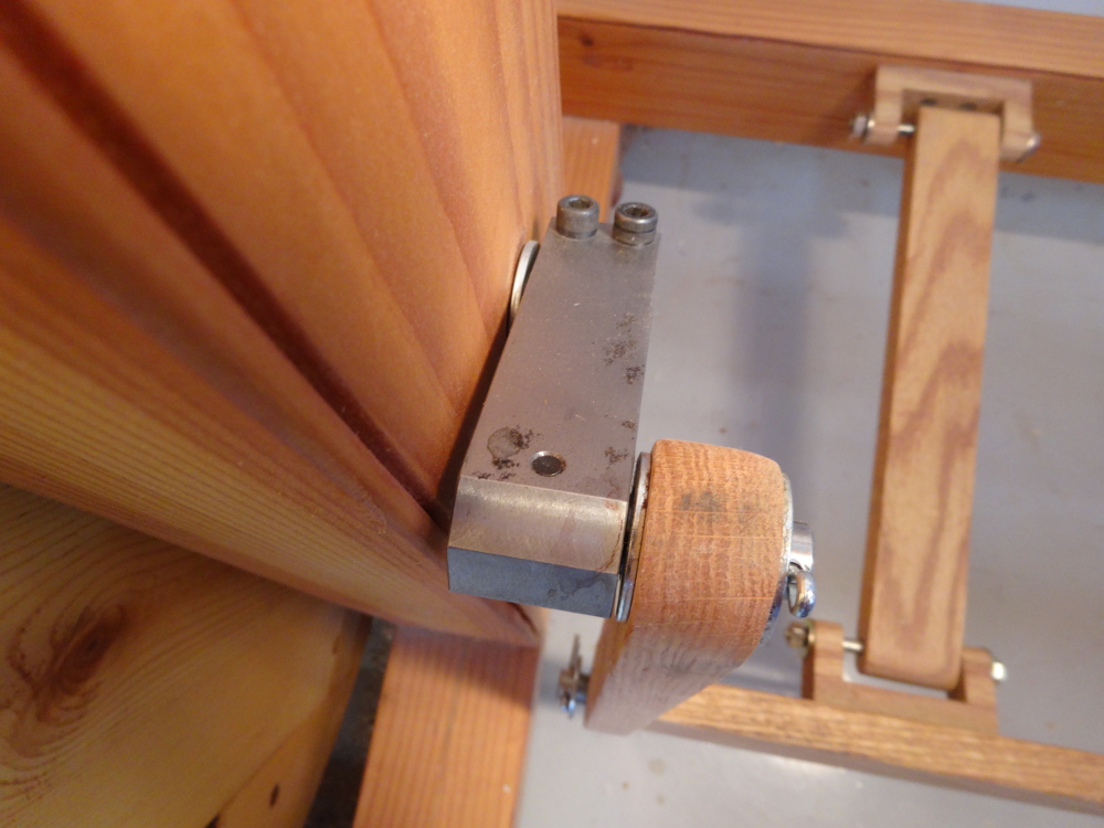
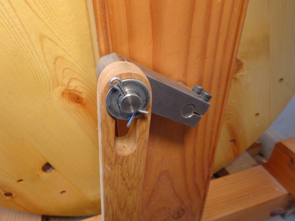
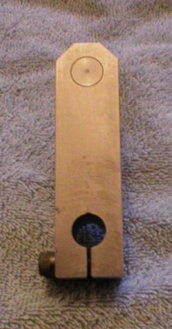
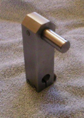
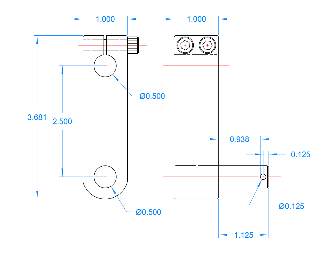
Photos and a drawing tell most of what you need to know to make one. If you have the metal working equipment to cut a block of steel, cut a slot in it, drill accurately, and tap some screw holes, you can make one similar. For what it’s worth, the distance between pivots was simply an estimate (a little more than a tenth the diameter of the flywheel) and has worked very well. Roger didn’t specify the size of the cap screws, but they look to be 1/4 by 20 by 1 inch long. The only other thing not shown on the drawing, that’s very visible in the photos, is a dowel pin that retains the crank pin. The retaining pin is probably not needed on this particular crank since Roger built it to such close tolerances that the crank pin probably took several tons of pressure to seat as a “press fit.”
When installing on the flywheel axle, be sure to go back and forth between the two screws, as they each affect the other’s tightness until they are really tight.
This crank has been very solid. I’ve got hours and hours of use on the lathe and ZERO, Nada, NO slippage from the crank. It simply works! Thanks again, Roger.
Bob,
I am researching local machine shops. Would this have to be made out of steel or could it be made from aluminum?
Thanks.
Josh
Josh,
I really don’t know; I’m not the engineer in this case, just a happy recipient of Roger’s talent.
Having said that, I think there are two factors, the strength of the threads for the clamping screws and the friction coefficient of where the crank wraps around the axle. Of the two, the threads seem more important. If there’s a risk of them stripping more easily with aluminum, the piece might have to be thicker to capture more thread turns.
Surely there can’t be much cost difference can there? Either material will need the same number of steps to make, and I imagine labor far outruns the cost of materials.
Ask your machinists and let us know what they say.
Bob,
I am a member of the Ohio Valley Woodturners Guild. I have recently built a 17th century pole lathe for our use in public demonstrations. It fascinates old and young alike! My next move into the lathe evolution chain is to build a treadle lathe for the same use. I have been doing a lot of research and there seems to be a gazillion plans and ideas out there on the net!! Yours has peaked my interest and I have decided to incorporate some of your ideas into its construction. I have to ask you about the belt tracking before I go any further. How does it track and does the radius edge (round) of the wheel and spindle drive help it to track and if so, could you please explain that to me. Is the alignment between the wheel and the spindle drive super critical? Any light you could shed on this would be appreciated! Thanks for posting this info out there for all to see! Gary Webster
Hi Gary,
It sounds like you’re having fun with public demos. Wonderful!
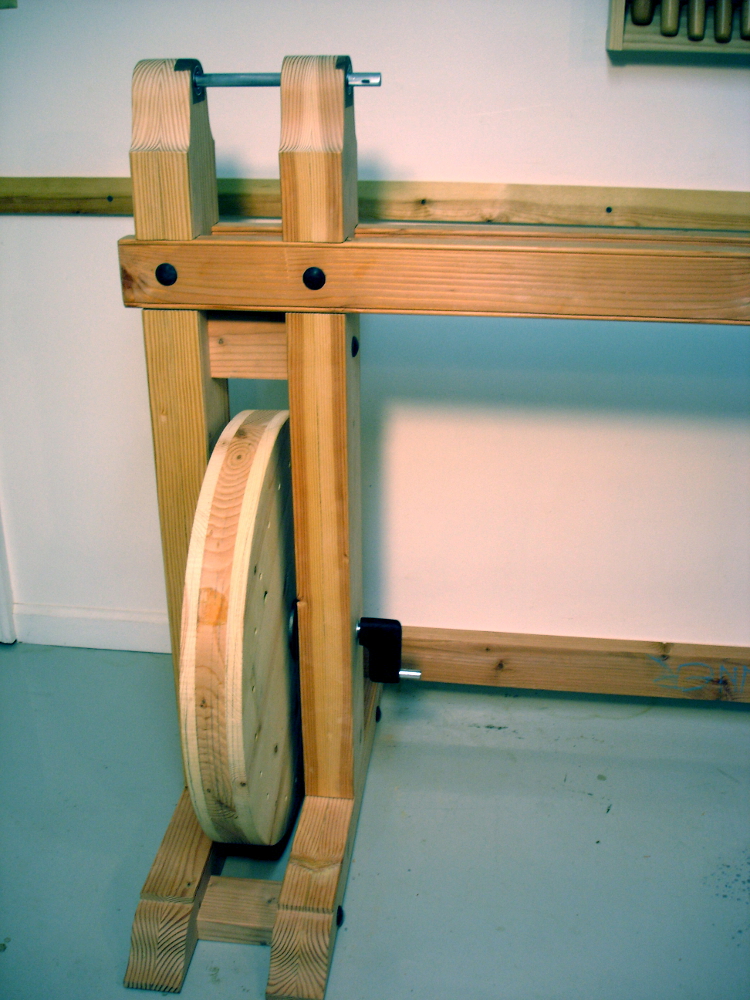
My belt tracks amazingly well. The belt is 2 inches wide. The wheel is 2 7/8 inches thick. There is NO crown on the rim of the wheel. It is flat. Since the wheel was hand made and the centers hand drilled, there’s a slight wobble, but so slight that the belt tracks without wandering off any edge.
The only radius on the wheel is a small chamfer at the edges to save catching splinters if bare legs get too close to the spinning wheel.
There IS a crown on the spindle drive. It is that crown which helps the belt track well. During no-load or light cutting, the belt stays up on the crown. Under heavier cutting, it veers off to one side or the other. A catch that stops the spindle finds the belt all the way off the crown and rubbing against the uprights. Relieve the catch or load and the belt climbs back to the top of the crown.
You can get a good view of it in operation in the video on this page: https://www.bob-easton.com/blog/2012/2468/
Next, you might ask about belt tension. As you see, I have no tension idler. I think of those as extra load, extra friction, and I don’t want the extra work when I’m pumping the thing. Instead, I first cut the belt to the length I thought would be tight enough and stitched it together. That was a bit loose. So, I un-stitched, shortened by 3/8 inch and stitched again. (Removing the head spindle to gain some slack space while stitching.) I did this twice to get it right. Midway between contact points, the belt can be deflected about 1 1/2 inches.
One last point… If your public demos stress historic re-enactment, give consideration to the kit of metal parts that Stephen Shepherd offers. They’re blacksmith made and appropriate for the early 19th century design. See this entry for details: https://www.bob-easton.com/blog/2013/2894/
Have fun with the project and post pictures somewhere to show us your results.
Bob, Thanks for the quick response!! Muchly appreciated! Got the wheel glued up last night. Will refine it today and start the mortise/tenon process. I completely understand the significance of historical duplication and preservation. However, since this will be a public display item and it will be open to a lot of hands on by adults and kids, I am going to incorporate some bearings and such into its construction to help maintain its longevity! There will be a displayed sign informing the spectators of the historical value along with why the tweeking of the design. Would like to send you a pic once it is completed.
Gary
We’ll be watching for your picture(s) Gary.
I have this sebastian treadle metal lathe. was converted to 110v. I was going to rework, (I am a retired Tool & Die Maker 40+ years) got sick with lung cancer.
I need to find a new home for this jewel.
John: 618-839-0774