• Skip to primary navigation
  • Skip to main content
  • Skip to primary sidebar
  • Skip to footer

Bob Easton

Chocolate powered woodworking

  • Home
  • Grinling Gibbons Tour

Treadle Lathe – Spindle

October 7, 2012 by Bob Easton 3 Comments

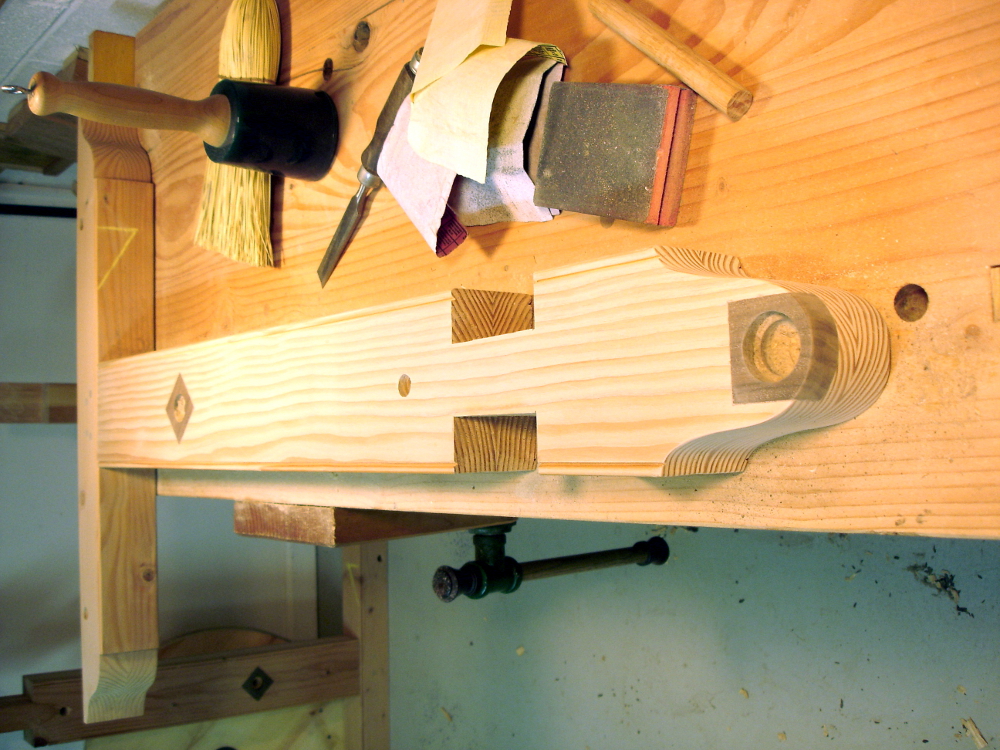
You saw a quick shot of the spindle in an earlier post. Let’s take a closer look.

photo of spindle bearings

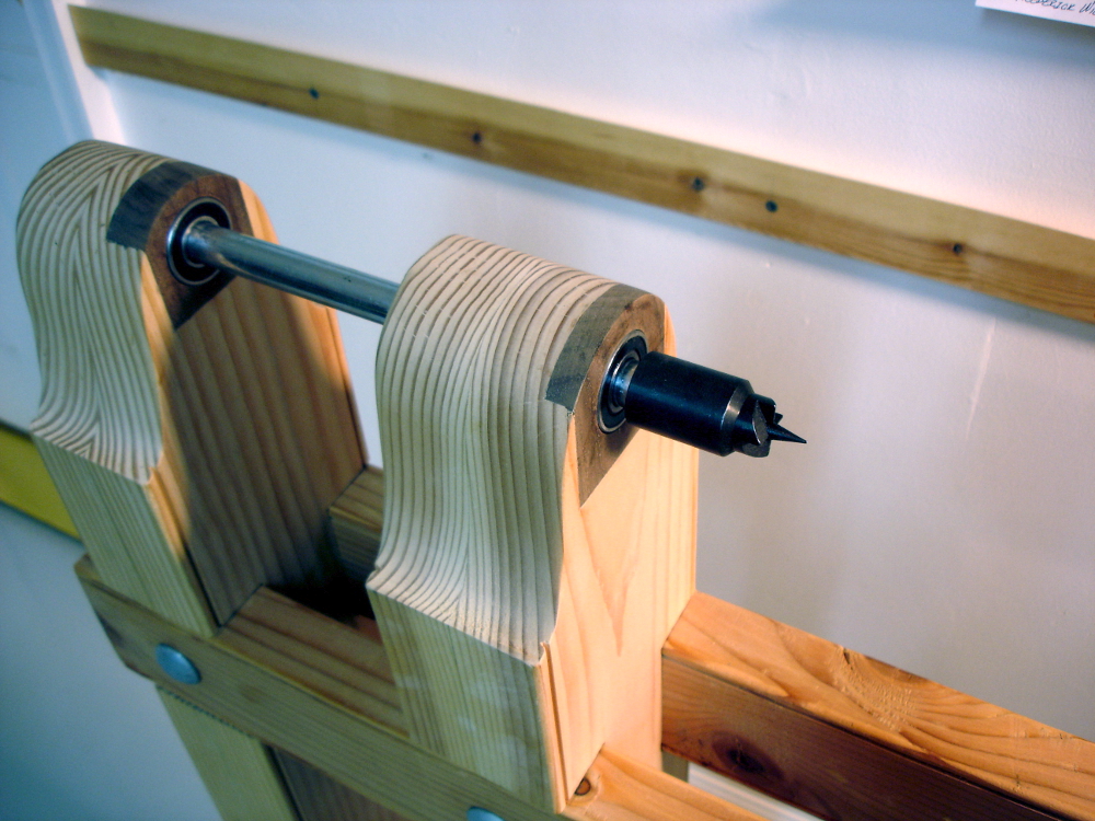
The spindle rides on 3 bearings. Two are ball bearings that sit in the walnut bearing blocks. The third bearing is a thrust bearing at the leftmost end. The thrust bearing offers a low friction way to absorb lateral pressure. The race that absorbs the pressure has a center hole too small for the spindle to pass through. The bearing ring in the middle is a very tight fit on the end of the shaft. The outer race has the same fit as the ball bearing. A photo details the parts for folks who haven’t seen this sort of thrust bearing.

photo of a fence finial

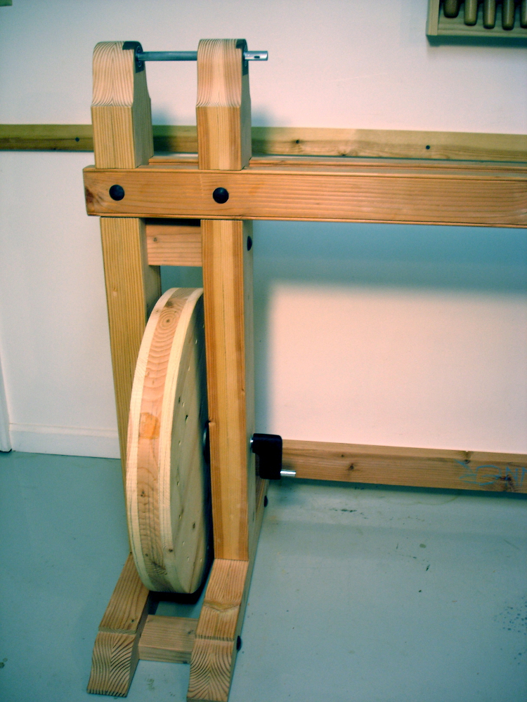
OK. What are we going to use for a drive pulley? There aren’t a whole lot of commonly available things of a decent diameter already having a 5/8″ hole bored through them. Hey, I could make one on a lathe! But, what to use to drive the lathe to make a drive pulley? Wander the aisles of the home center, asking “what about this, that, the other thing over there?”

Found it! A finial for a fence post looks like just the thing. Cut off the ball part. Bore a hole through it.

photo of temporary drive pulley

Fix it to the spindle, and get going. …and only $3.42. With all the boring I’ve done with the brace and Russel Jennings augers, I’ve gotten fairly good at putting holes near where I want them. Finding the center of a not-so-round pressure treated ball, and then drilling dead on the center was a near impossibility, and I lived up to that expectation. It’s not perfect. Yes Jeremy, it does wobble a bit, but it’s not headed for 70mph. Fixing it to the spindle is done with a couple of 1/8″ holes driven into the ball and partly into the spindle and #8 by 1-1/2″ wood screws. Crude but practical for a very temporary drive pulley.

Filed Under: Shopmade, treadle lathe

Treadle Lathe – Treadle and First Turning

October 3, 2012 by Bob Easton 13 Comments

Roger Davis is a fortune teller, and a fellow Hoosier.

photo of new crank and part of the linkage

Roger and I met quite awhile back over on the Sawmill Creek forums talking about, what else, old tools. Not long after I published the last entry, Roger advised that the walnut crank probably wouldn’t last long. Now, it hasn’t actually failed but it didn’t take long for a bit of wobble to develop. Roger is a fellow woodworking enthusiast who also has day-job metal working skills and the equipment for prototyping aerospace instrumentation. Roger offered to make a “bulletproof” steel crank and I took him up on the offer. I’m absolutely amazed that he offered and acted so quickly. The crank is here and already in use. THANK YOU Roger!

By the way, for the spalted maple fans, be aware that there’s such a thing as spalted steel. This crank has a bit of spalting which I consider early onset patina.

The Treadle Mechanism

photo of complete treadle mechanism

When I was much younger and more interested in high performance automobiles, one of the things I learned about was “unsprung weight.” That’s the weight of the car in the wheels, axles and undercarriage that isn’t moderated by the suspension system. A lot of unsprung weight dampens a car’s performance. The lower the amount of unsprung weight, the better performance can be tuned. This lathe takes that approach with the treadle. I’ve seen a lot of treadle lathes that have huge heavy treadle mechanisms. It seems to me that the effort that goes into operating a heavy treadle has the same dampening effect as excessive unsprung weight in cars. I can appreciate how a heavy flywheel adds momentum, but not if it has to drag along the dead weight of a heavy treadle. The lighter treadle was part of what drew me to this design.

photo of linkage near the wheel

Three lightweight parts comprise the moving components, the treadle itself, a Pittman link, and a spacer bar that keeps the treadle parallel to the center line of the lathe. All three are of oak approximately 3/4″ by 1-1/2″ in measure. The treadle pivots on a 1/2″ diameter pin that’s held in the walnut block on the foot of the right leg. The pivot hole itself is 3/4″ diameter providing enough play for easy operation. The driving end of the pedal holds another 1/2″ diameter pin that engages the Pittman link. The bottom hole on the Pittman link is also 3/4″ diameter, allowing for a lot of angular movement. At the top of the Pittman link is a slot that is “a whisker” larger than 1/2″ wide, enough to ride freely on the crank’s 1/2″ diameter drive pin. Two u-shaped oak blocks anchor the spacer bar. The anchor pins are 1/4″ bolts fitted in 1/4″ holes in the blocks. The pivot holes in the spacer bar are 5/16″. Thinking these parts might need lots of wiggle room, I tried a much loser version and ended up with a lot of clunking. The tighter version runs smoothly and without any binding.

As before: Il meccanismo è molto scorrevole!

First Turning – a 24 inch object

photo: Truing the flywheel

A couple of posts back, I mentioned that the flywheel was cut round using a jig on the band saw. Well, that “round” was approximate. It wanted some truing, not a lot but enough to make me wonder about how well a belt would track. How to get it trued up? Makeshift time!

Finding a “tool rest” of an appropriate height was the first challenge. What the photo shows is an alternate use for the pair of saw benches I made ages ago. Flop them over on their sides and stack them “just so,” and the result is something good for supporting a newly arrived round nosed scraper. Not having a readily available treadling apprentice, I parked a chair beside the upturned saw benches, sat down, and treadled while leaning over and holding the chisel.

The wheel is now round. The drive belt won’t have to put up with a roller coaster ride. If you watch the wheel turn, you’ll see some side-to-side wobble, for which there are two responses: don’t watch, and it’s not enough to affect operation. 🙂

Filed Under: Shopmade, treadle lathe

Treadle Lathe – Head End – molto scorrevole!

September 22, 2012 by Bob Easton 13 Comments

phot of leg with two inset bearing blocks

More spinning things! There are lots of little step-by-step things since the last time. Summarized, two axles are now running on ball bearings and held in an assembly of two legs. Simple.

The left leg holds two bearing blocks. Both are set in only as deep as they need be. The flywheel axle and the headstock spindle do not run completely through the left leg. There’s a single bearing for the flywheel axle.

photo of spindle

The headstock spindle has two bearings. Leftmost is a thrust bearing which absorbs lateral pressure on the spindle. Immediately next to it is a ball bearing for the radial load.

The flywheel axle is 1/2″ steel rod, common stuff from the home center. The headstock spindle is also common 5/8″ steel rod. I used that size because it is the same as a ShopSmith spindle and several parts are available for that size spindle (see the post 2 previous to this for actual part numbers).

photo of assembled legs, flywheel and spindle

The right leg, of course, has through holes for both the flywheel axle and the headstock spindle. The bearing for the flywheel axle is on the inside / left face of this leg, making both flywheel bearings close to the wheel itself. The headstock spindle bearing is on the outside / right face of the leg.

The legs are bolted together with 3 carriage bolts, each running thorough a spacer block, two through the feet and the third just below the rails. It’s solid!

Last, there’s a crank piece made of walnut. Remember, the blacksmith moved away, and I don’t have enough metal working skills to bend cranks in 1/2″ steel rod. So, I used a block of walnut, and pinned it to the flywheel axle and the crank stub with pins made from 8-penny nails.

And… yes, that’s a pile of sandpaper (YIKES!) in one of those photos. Hate the stuff. But the wood needed it.

Result: Il meccanismo è molto scorrevole! (http://translate.google.com/#it|en| is your friend)

Filed Under: Shopmade, treadle lathe

  • « Go to Previous Page
  • Page 1
  • Interim pages omitted …
  • Page 46
  • Page 47
  • Page 48
  • Page 49
  • Page 50
  • Interim pages omitted …
  • Page 128
  • Go to Next Page »

Primary Sidebar

Footer

Recent Posts

  • New Frame Saw / Scroll Saw
  • Lamppost Sign
  • Goodbye PayPal – Goodbye Bob’s eBooks
  • Anarchist’s Workbench is Done
  • Why we keep offcuts…

Categories

  • About
  • Artwork
  • Boatbuilding
  • Boating
  • bowl carving
  • Boxmaking
  • Clocks
  • Drawings
  • eBook
  • etude
  • Eva Too
  • Eva Won
  • Fiddlehead
  • Fiddlehead model
  • Flying
  • frame saw
  • gilding
  • green woodworking
  • Grinling Gibbons
  • Guns
  • Hand tools
  • Humor
  • kerfing plane
  • Lettercarving
  • Mill Creek 13
  • Model building
  • Power tools
  • Rant
  • resawing
  • scroll saw
  • Shopmade
  • sign painting
  • Stonework
  • Swimming
  • Technology
  • The Wall
  • treadle lathe
  • Uncategorized
  • VSD
  • Woodcarving
  • Woodturning
  • Woodworking
  • workbench

Other stuff

  • About
  • Contact
  • Privacy Policy

Copyright ©2024 · Bob Easton · All Rights Reserved